In the directory structure, find the folder called faq. In it you can create a .md file for your contribution.
Write your contribution using markdown. You can include images as well as links. There are many tutorials on Markdown but you most likely already know it.
If you want the title to be something other than the file name, then add:
as the first few lines of the file 5. Git add, commit and push your changes.
Note
Brand new files (vs. edits) will not appear in the directory until it is rebuilt by rpsalas@brandeis.edu so send them an email!
---
title: Gooder Title
author: Pito Salas
description: nicer subtitle
order: where does this one appear in order
status: obsolete|new|tophit
date: month-year
---
Advanced: Help me troubleshoot weird camera problems
For advanced users who are trying to tix weird problems
Ensure that the camera is enabled and there is enough GPU memory:
Add the following lines to the /boot/firmware/config.txt file:
start_x=1
gpu_mem=128
And then reboot. Note that the config.txt file will say that you should not modify it and instead make the changes in a file called userconfig.txt. However I found that the userconfig.txt file is not invoked. So I added the lines above directly to config.txt.
Check the amount of gpu_memory
It should show 256 or whatever number you put there.
Camera Calibration
How to calibrate a camera before using computer vision algorithms (e.g. fiducial detection or VSLAM)
Question
I want to run a computer vision algorithm on my robot, but I'm told that I need to calibrate my camera(s) first. What is camera calibration, and how can I do it?
vcgencmd get_mem gpu
What is Camera Calibration?
Camera calibration is the act of determining the intrinsic parameters of your camera. Roughly speaking, the intrinsic parameters of your camera are constants that, in a mathematical model of your camera, describe how your camera (via its interior mechanisms) converts a 3D point in the world coordinate frame to a 2D point on its image plane.
Intrinsic parameters are distinct from extrinsic parameters, which describe where your camera is in the world frame.
So, since calibration deals with the intrinsic parameters of your camera, it practically doesn't matter where you place your camera during calibration.
To hear more about the basics of camera calibration, watch the following 5-minute videos by Cyrill Stachniss in order:
This video, also by Cyrill Stachniss, is a deep dive into Zhang's method, which is what the camera_calibration package we discuss below uses under the hood.
How Can I Calibrate my Camera?
This note describes two ways you can calibrate your camera. The first is by using the camera_calibration ROS package. This is the easier approach, since it basically does almost all of the work for you. The second is by using OpenCV's library directly, and writing your own calibration code (or using one in circulation).
The camera_calibration Package
This guide assumes you've already got your camera working on ROS, and that you're able to publish camera_info and image_raw topics for the camera. If you need to set up a new usb camera, see this entry in our lab notebook.
First, let's install the package:
Second, print out this checkerboard on a letter-sized piece of paper.
Third, tape the corners of the paper to a firm, flat surface, like the surface of a piece of cardboard.
Fourth, measure a side of a single square, convert your measurement to millimeters, and divide the result by 1000. Let's call your result, RESULT.
Now, let the number of rows of your checkerboard be M and its number of columns N. Finally, let's say your camera node's name is CAM, such that, when you connect it with ROS, it publishes the /CAM/camera_info and /CAM/image_raw topics. Now, after ensuring that these two topics are being published, execute:
WARNING The two sections stated above are the only ones you actually want to follow in the official tutorial. Much of the rest of the material there is outdated or misleading.
Here's a video of what a successful calibration process might look like.
OpenCV
Sometimes, you might want to use object detection or use certain algorithms that require a camera such as VSLAM. These algorithms usually require a very good calibration of the camera to work properly. The calibration fixes things like distortion by determining the camera’s true parameters such as focal length, format size, principal point, and lens distortion. If you see lines that are curved but are supposed to be straight, then you should probably calibrate your camera.
Usually this is done with some kind of checkerboard pattern. This can be a normal checkerboard or a Charuco/Aruco board which has some patterns that look like fiducials or QR codes on it to further help with calibration. In this tutorial, we’ll be using a 7x9 checkerboard with 20x20mm squares: checkerboard pdf.
The most ideal way to do is to print the checkerboard on a large matte and sturdy piece of paper so that the checkerboard is completely flat and no reflections can be seen on it. However, it’s okay to just print it on a normal piece of paper as well and put it on a flat surface. Then, take at least ten photos with your camera from a variety of angles and positions so that the checkerboard is in all corners of the photos. Make sure the whole checkerboard is seen in each picture. Save those photos in an easy to find place and use the following to get your intrinsic calibration matrix.
The code I used was this opencv calibration. It also has more notes and information about what the information you are getting is.
Step by step:
print out checkerboard pattern
take at least 10 photos of the checkerboard at a variety of angles and positions (see image 1 for examples) and save in an easy to access place
download/copy the opencv calibration code and run it after changing the folder path
get the intrinsic matrix and distortion and enter it into whatever you need
image
Image 1: some examples of having the checkerboard cover all corners of the image
rosrun camera_calibration cameracalibrator.py --size MxN --square
RESULT image:=/CAM/image_raw camera:=CAM
Advanced: Help me troubleshoot weird build problems
For advanced users who are trying to tix weird problems
Notes
You really need to know what you are doing when you are dealing at this level.
Radical Cleanup
It turns out that it is safe to delete the build and devel subdirectories in ROS.
Sometimes this helps:
Another way
First: lean your build by running "catkin_make clean" in the root of your workspace.
Second: remake your project with "catkin_make"
Third: re-source the devel/setup.bash in your workspace.
cd ~/catkin_ws
rm -rf build/ devel/
catkin_make
source devel/setup.bash
Computer Vision With Yolo8a
Yolo8 is a cutting-edge, state-of-the-art (SOTA) model that builds upon the success of previous YOLO versions and introduces new features and improvements to further boost performance and flexibility. YOLOv8 is designed to be fast, accurate, and easy to use, making it an excellent choice for a wide range of object detection and tracking, instance segmentation, image classification and pose estimation tasks. It is a powerful model that can be used to detect multiple objects in an image.
It has been wrapped into a user-friendly python package Ultralytics (https://docs.ultralytics.com/). To detect objects of interest, the pre-trained model yolo8 can be used. Or one can customize the yolo8 model by training it with provided train image data. Here the website Roboflow (https://roboflow.com/) has a variety of object datasets, e.g. traffic sign dataset (https://universe.roboflow.com/usmanchaudhry622-gmail-com/traffic-and-road-signs/model/1). Once the dataset is downloaded and the Ultralytics package is installed, the yolo8 model can be trained easily:
Where the traffic_sign.yaml is the path to the yaml file inside your downloaded dataset from roboflow. You have the options to use various yolo8 models. See Detection Docs for usage examples with these models.
The larger the model is, the higher the latency will present in the ros node that holds the model. Therefore, the smaller model should be used as long as the model works for the objects of interest.
This is a quick ann simply way to train a customized model that is powerful in objects detection of robot vision.
Very handy command in vscode that makes this really easy!
Author: Michael Jiang
How do I download files from my online VSCode to my local computer?
While the online VSCode does not offer a way to download entire folders and their contents with one click, there is a non-obvious functionality that allows you to download individual files directly from VSCode.
Right click the desired file and select 'Download' from the menu. The file will download to your default download location on your computer.
You will be able to now access the files from your local system and submit them to Gradescope. To submit packages like this, you can set up a Git repository and push the files there, or you can individually download each file in the package using this method, arrange them properly, and submit it on Gradescope.
Connecting to the robot
plug in battery and turn on robot with the power switch, give it a moment and wait for the lidar to start spinning.
run tailscale status | grep <name> to find the robot’s IP address. Replace with the name of the robot you are trying to connect to.
image
go to .bashrc in my_ros_data folder and get it to look like this with your robot’s name and IP address instead:
Open a new terminal and you should see:
You can then ssh into the robot, ssh ubuntu@100.117.252.97 (enter your robot’s IP) and enter the password that is in the lab.
Once onboard the robot, enter the command bringup which starts roscore and the Turtlebot’s basic functionalities. For the Platform robots, run this: roslaunch platform full_bringup.launch
When you're done, run sudo shutdown now onboard the robot (where is ran bringup) and then turn off the robot with the power switch.
Basic Chatgpt ROS interface
by Kirsten Tapalla - Spring 2023
This is a quick guide to connecting to ChatGPT and getting it to generate a message that you can publish to a topic for use in other nodes.
Necessary Imports:
import requests: used to connect to the internet and post the url to connect to ChatGPT
import rospy: used to publish the response from ChatGPT to a topic
from std_msgs.msg import String: used to publish the response as a ros String message
Node Initialization and Variables/Parameters:
Since you want to publish the message into a topic, you will have to initialize a rospy node withing your file using rospy.init_node('ENTER-NODE-NAME-HERE').
You will also want to initialze a rospy Publisher with the name of the topic you would like to publish the data to, for example: text_pub = rospy.Publisher('/chatgpt_text', String, queue_size=10).
If you would like to be able to change the prompt you are passing it when running the node, you should add a line allowing you to do this by initializing an input string to get the parameter with the name of what you would like to use to specify the input message you would like to pass it.
ChatGPT Information:
Headers:
To be able to access ChatGPT, you will need to include the following information in your 'header' dictionary: Content-Type and Authorization. Below is an example of what yours might look like:
headers = { 'Content-Type': 'application/json', 'Authorization': 'Bearer INSERT-YOUR-OPENAI-API-KEY-HERE',}
Data:
This will include the information you will want to pass into ChatGPT. The only required field will be specifying the model you want to use, but since you are passing in a prompt, you will also want to include that as well. You will be able to specify the maximum amount of tokens you want ChatGPT to generate, but the best way to get the full output messeage from ChatGPT is to enter the maximum amount for the model you are using. For example, as you can see below I am using the 'text-davinci-003' model, and the maximum tokens that this model can generate is 2048. Furthermore, you can adjust the sampling temperature, which will determine how creative the output of ChatGPT will be. The range goes between 0-2, and higher values will cause it to be more random, while lower values will cause it to be more focused and deterministic. An example of a request body you can make is shown below:
data = { 'model': 'text-davinci-003', 'prompt': input_string, 'max_tokens': 2048, 'temperature': 0.5,}
Getting and Publishing the Response
To get the response for your input message from ChatGPT, include the following line in your code response = requests.post(url, headers=headers, json=data). Note that if you are using different names for your variables, you will want to pass in those names in place of 'headers' and 'data'.
To publish your output, you will want to make sure that your request went through. If it did, you will be able to get the output from the json file that was returned in the response variable. An example of how to do this is shown below:
if response.status_code == 200: generated_text = response.json()['choices'][0]['text'] text_pub.publish(generated_text)
By doing all of the steps above, you will be able to connect to ChatGPT, pass it a prompt, and publish its response to that prompt to a topic in ros.
For example, do this by writing input_string = rospy.get_param('~chatgpt_prompt')
When setting up your launch file later on, you will want to include a line to handle this argument. This can be done by including arg name="chatgpt_prompt" default="ENTER-YOUR-DEFAULT-PROMPT-HERE" into your launch file. You can set the default to whatever default prompt you would like to be passed if you are not giving it a specific one.
You will also want to add this line into your code to to specify the URL going that will be used to connect to ChatGPT: url = 'https://api.openai.com/v1/completions'. Since the chat/text completions model is what we are using the get the output responses, the URL specifies 'completions' at the end.
After that, open a new terminal (you’ll be in real mode again) and run your program!
To go back to simulation mode, go back to .bashrc and uncomment the settings for simulation mode and comment out the settings for a physical robot. Or type the command sim in the terminal. You will need to do this in every terminal that you open then. To switch to real mode, type command real.
image
image
Creating and Executing Launch Files
by Helen Lin edited by Jeremy Huey
Introduction
This guide shows you how to create launch files for your code so that you can launch multiple nodes at once rather than running each node individually.
Step 1
Open a new terminal window and navigate to a package you want to create a launch file in. Create a folder called 'launch'.
mkdir launch
Step 2
Navigate to the launch directory and create a new launch file ending in .launch. Replace 'name' with the name of your launch file.
touch name.launch
Step 3
Add the following code and fill in the parameters within the double quotes.
Here is an example of what the node will look like filled in, using code from the Mini Scouter project:
The pkg name can be found in the package.xml. Eg.
Step 4
Make sure you have run the following command on all of the files used in the launch file so they can all be found by ROS launch. Replace 'name' with the name of the python file.
chmod +x name.py
Change the permissions of the launch file as well by going to the launch directory and running the following command. Replace 'name' with the name of the launch file.
chmmod +x name.launch
Step 5
Open a new terminal window and run the following command. Replace 'package_name' with the name of the package and 'name' with the name of the launch file.
roslaunch package_name name.launch
For example, to run the Mini Scouter launch file:
roslaunch mini_scouter teleop.launch
All of the nodes you specified in the launch file should now be running.
Optional, launch process in new window
To have a node launch and open in a new window, such as to run things like key_publisher.py, you can modify the line to include this: <node pkg="object_sorter" type="key_publisher.py" name="key" output="screen" launch-prefix="xterm -e"/> You must then run in terminal:
More info on launch files
To continue to get more information on launch files, go to here: labnotebook/faq/launch-files.md
The detection of edges in image processing is very important when needing to find straight lines in pictures using a camera. One of the most popular ways to do so is using an algorithm called a Canny Edge Detector. This algorithm was developed by John F. Canny in 1986 and there are 5 main steps to using it. Below are examples of the algorithm in use:
Pre Canny
Post Canny
The second image displays the result of using canny edge detection on the first image.
Steps to Edge Detection:
Apply to smooth image
Find intensity gradients of image
Apply gradient magnitude thresholding or lower bound cut-off suppression to remove false results
Track edge by surprisessing weak edges so only strong ones appear
Application of Canny Edge Detection
The below function demonstrates how to use this algorithm:
First, the image is converting into something usable by cv. It is then grayed and the intensity gradient for the kernel is found
The image is then blurred for canny preparation.
The lower and upper bounds are decided and the Canny algorithm is run on the image. In the case of this function, the new image is then published to a topic called "canny mask" for use by another node.
The above code was created for use in a project completed by myself and fellow student Adam Ring
This is a quick guide to finding the HSV values for any color that you may need for you project. We found this particularly helpful for following a line.
Prerequisite
A robot with a camera
VNC
Basic Steps
Connect your robot. You can find the guide
Once your robot is connected, open vnc and run cvexample.py file in the terminal.
In a seperate terminal, run rqt.
In rqt window, click Plugning -> Dynamic Reconfigure
Click cvexample and the hsv slides should pop up.
Adjust the sliders to find the hsv values for your desired colors.
In a seperate terminal, run rqt_image_view to get a larger frame of the camera image. This is optional.
An overview of the utilization of the iPhone for more accurate GPS data
Brandon J. Lacy
Overview
The utilization of GPS data on a robot is a common requirement within projects. However, a majority of hardware components that can be configured with the robot produce lackluster results. The iPhone uses sophisticated technology to produce more accurate GPS data, which makes it a prime candidatee for situation in which a robot is in need of accurate information. The application, GPS2IP, uses the technology of the iPhone and communicates it over the internet. Through this application and the iPhone technology an accurate vehicle to produce GPS data is obtained.
GPS2IP
The application is solely available on iOS. No research was conducted on applications on Android that produce similar functionality. There are two versions of the application on the App Store: GPS2IP ($8.99) and GPS2IP Lite (Free). The free version only allows transmission for 4 minutes before automatically turning off. The paid version has no restrictions.
Walkthrough
iPhone Configuration
Turn Off Auto-Lock
Settings > Display & Brightness > Auto-Lock > Never
GPS2IP Configuration
Enable GPS2IP
Open GPS2IP > Toggle On "Enable GPS2IP" Switch
NMEA Message Type
Open GPS2IP > Settings > NMEA Messages to Send > Only Toggle On "GLL" Switch
Python Code
#!/usr/bin/env python
'''
A module with a GPS node.
GPS2IP: http://www.capsicumdreams.com/gps2ip/
'''
import json
import re
import rospy
import socket
from std_msgs.msg import String
class GPS:
'''A node which listens to GPS2IP Lite through a socket and publishes a GPS topic.'''
def __init__(self):
'''Initialize the publisher and instance variables.'''
# Instance Variables
self.HOST = rospy.get_param('~HOST', '172.20.38.175')
self.PORT = rospy.get_param('~PORT', 11123)
# Publisher
self.publisher = rospy.Publisher('/gps', String, queue_size=1)
def get_coords(self):
'''A method to receive the GPS coordinates from GPS2IP Lite.'''
# Instantiate a client object
with socket.socket(socket.AF_INET, socket.SOCK_STREAM) as s:
s.connect((self.HOST, self.PORT))
# The data is received in the RMC data format
gps_data = s.recv(1024)
# Transform data into dictionary
gps_keys = ["message_id", "latitude", "ns_indicator", "longitude", "ew_indicator"]
gps_values = re.split(',|\*', gps_data.decode())[:5]
gps_dict = dict(zip(gps_keys, gps_values))
# Cleanse the coordinate data
for key in ['latitude', 'longitude']:
# Identify the presence of a negative number indicator
neg_num = False
# The GPS2IP application transmits a negative coordinate with a zero prepended
if gps_dict[key][0] == '0':
neg_num = True
# Transform the longitude and latitude into a format that can be utilized by the front-end web-client
gps_dict[key] = float(gps_dict[key]) / 100
# Apply the negative if the clause was triggered
if neg_num:
gps_dict[key] = -1 * gps_dict[key]
# Publish the decoded GPS data
self.publisher.publish(json.dumps(gps_dict))
if __name__ == '__main__':
# Initialize a ROS node named GPS
rospy.init_node("gps")
# Initialize a GPS instance with the HOST and PORT
gps_node = GPS()
# Continuously publish coordinated until shut down
while not rospy.is_shutdown():
gps_node.get_coords()
Finding correct color for line following
Line follower may work well and easy to be done in gazebo because the color is preset and you don't need to consider real life effect. However, if you ever try this in the lab, you'll find that many factors will influence the result of your color.
Real Life Influencer:
Light: the color of the tage can reflect in different angles and rate at different time of a day depend on the weather condition at that day.
Shadow: The shadow on the tape can cause error of color recognization
type of the tape: The paper tage is very unstable for line following, the color of such tape will not be recognized correctly. The duct tape can solve most problem since the color that be recognized by the camera will not be influenced much by the light and weather that day. Also it is tougher and easy to clean compare to other tape.
color in other object: In the real life, there are not only the lines you put on the floor but also other objects. Sometimes robots will love the color on the floor since it is kind of a bright white color and is easy to be included in the range. The size of range of color is a trade off. If the range is too small, then the color recognization will not be that stable, but if it is too big, robot will recognize other color too. if you are running multiple robots, it might be a good idea to use electric tape to cover the red wire in the battery and robot to avoid recognizing robot as red line.
So if we use color pick we find online, we may need to rescale it to opencv's scale.
OpenCV and HSV color:
Opencv use hsv to recognize color, but it use different scale than normal.
Here is a comparison of scale:
normal use H: 0-360, S: 0-100, V: 0-100
Opencv use H: 0-179, S: 0-255, V: 0-255
Claw Movement
How to use the claw
This FAQ will guide you through the process of using the claw in our color sorting robot project. The applications for the claw are endless, and this guide will allow you to easily write code for use of the claw on a robot. The instructions below are written for ROS and Python.
How do I set up the robot with the claw?
Make sure you are connected to a robot with a claw. As of now, the only robots with a claw are the platform robots in the lab.
How do I import the necessary libraries?
Import 'Bool' from 'std_msgs.msg':
How do I create a publisher for the claw?
Create a publsiher that publishes commands to the claw:
This code creates a publisher called 'servo_pub' that publishes to the '/servo' node and sends a Bool value.
How do I write code to open or close the claw?
Write code to open or close the claw:
FAQ
Q: Can I control the speed of the claw?
A: The code provided does not control the speed of the claw. You will need to modify the code and use a different message type to control the speed.
Q: Can I use this code for other robots with a claw?
A: There are two robots as of right now with the claw attachment, both are platform robots. One of the claws is a big claw while the other one is a smaller claw. Both can be used for different applications and in both cases, the above code should work.
Q: How do I open and close the claw at specific times?
A: As long as you have a publisher, you can publish a command to open or close a claw at any time during the main loop of your program. You can have multiple lines of codes that opens or closes the claw multiple times throughout a program or you can just write code to have the claw open once. It's up to you.
from std_msgs.msg import Bool #Code to import Bool
servo_pub = rospy.Publisher('/servo', Bool, queue_size=1) #Code for publisher
About roubles that you may run into if you are trying to connect to bluetooth using linux or raspberry pi
The linux bluetooth struggle
There are some troubles that you may run into if you are trying to connect to bluetooth using linux or raspberry pi, so this is a guide to try and overcome those difficulties. Hopefully, it is helpful.
Install Pipewire
Run the following commands to install Pipewire and disable PulseAudio.
To check that Pipewire is properly installed, run
If this doesn't work, try restarting Pipewire or your computer:
If you get the error: Connection failure: Connection refused
Steps taken to get bluetooth headset to run
Check the status of your bluetooth:
To connect your bluetooth device, run the following commands:
Set profile
After this, run:
You'll get a list of devices and the bluetooth device will be in the form of bluez_card.84_6B_45_98_FD_8E
From what I understand, most bluetooth headsets have two different profiles: ad2p and headset-head-unit. To use the microphone, you will need to set the card profile of your bluetooth device to headset-head-unit
Then, test whether or not the device is recording and playing properly:
Change default
You can set the default input and output devices using the following commands.
Given two coordinates in a 2-dimensional plane and your robots' current direction, the smart rotation algorithm will calculate your target angle and return whether your robot should to turn left, turn right, or go straight ahead to reach its navigation goal.
How It Works:
Inputs: posex1 is a float that represents the x-axis coordinate of your robot, posey1 is a float that represents your robot's y-axis coordinate. posex2 and posey2 are floats that represent the x and y of your robot's goal. Lastly, theta represents your robot's current pose angle.
Firstly, the angle_goal from your robot's coordinate (not taking its current angle into account) is calculated by finding the arc tangent of the difference between the robot's coordinates and the goal coordinates.
In order to decide whether your robot should go left or right, we must determine where the angle_goal is relative to its current rotational direction. If the angle_goal is on the robot's left rotational hemisphere, the robot should rotate left, otherwise it should rotate right. Since we are working in Radians, π is equivilant to 180 degrees. To check whether the angle_goal is within the left hemisphere of the robot, we must add π to theta (the robot's current direction) to get the upperbound of the range of values we want to check the target may be included in. If the angle_goal is between theta and that upper bound, then the robot must turn in that direction to most efficiently reach its goal.
Consider This Example:
If your robot is at (0,0), its rotational direction is 0, and it's target is at (2,2), then its angle_goal would equal = 0.785. First we check whether its current angle's deviation from the angle_goal is significant by finding the difference and seeing if its larger than 0.1. If the difference between the angles is insignificant the robot should go straight towards its goal. In this case however, angle_goal - theta (0.785 - 0) is greater than 0.1, so we know that we must turn left or right to near our angle_goal. To find out whether this angle is to the left or the right of the robot's current angle, we must add π to its current angle to discover the point between its left and right hemispheres. In this case, if the angle_goal is between theta and its goal_range, 3.14 (0(theta) + π), then we would know that the robot must turn left to reach its goal.
However, if theta (your robot's current direction) + π is greater than 2π (maximum radians in a circle) then the left hemisphere of your robot is partially across the 0 radian point of the circle. To account for that case, we must calculate how far the goal range wraps around the circle passed the origin. If there is a remainder, we check whether the angle_goal is between theta and 2π or if the angle_goal is present within the remainder of the range that wraps around the origin. If either of these conditions are met then we know that your robot should turn left to most efficiently arrive at its goal, otherwise it should turn right.
from math import atan2
import math
def smartRotate(posex1, posey1, posex2, posey2, theta):
inc_x = posex2 -posex1
inc_y = posey2 -posey1
angle_goal = atan2(inc_y, inc_x)
# if angle_to_goal < 0:
# angle_to_goal = (2* math.pi) + angle_to_goal
print("angle goal = ",angle_goal)
goal_range = theta + math.pi
wrapped = goal_range - (2 * math.pi)
if abs(angle_goal - theta) > 0.1:
print(theta)
print("goal_range = ",goal_range)
if (goal_range) > (2 * math.pi) and (theta < angle_goal or angle_goal < wrapped):
print("go left")
elif (goal_range) < (2 * math.pi) and (theta < angle_goal and angle_goal < goal_range):
print("go left")
else:
print("go right")
else:
print("go straight")
smartRotation(0,0,2,2,0)
How do I control AWS RoboMaker?
Introduction
Amazon Web Services RoboMaker is an online service which allows users to develop and test robotic applications online. Robomaker has a number of advanced features, but this notebook page will focus on developing nodes and simulating them in Gazebo. To use RoboMaker, you will also need to use AWS S3 and Cloud9.
Getting started
Create an AWS root account if you do not already have one. A free tier account will suffice for getting started, though make note that under a free tier membership you will be limited to 25 Simulation Units (hours) for the first twelve months.
Once you have an AWS account, you should create an IAM for your account. AWS recommends not using your root user account when using services like RoboMaker. . Remember the username and password of the account you create. Additionally, save the link to where you can log in with those credentials.
Going forward, you should be logged in with your IAM account. Log into AWS with your IAM, then proceed.
Amazon Documentation and Mini Tutorial
RoboMaker has a limited documentation set that can help you use the software. The “getting Started” section can help familiarize yourself with the software by working with a sample application. .
Creating an S3 bucket
From the AWS Management Console, type “S3” into the “find services” field and click on S3 in the autofill list below the entry box. From the S3 Management Console, click “Create Bucket”
On the first page, enter a name for your bucket. Under region, make sure that it is US East (N Virginia), NOT US East (Ohio), as RoboMaker does not work in the Ohio region.
Skip step 2, “configure options”
In step 3, “Set Permissions”, uncheck all four boxes
This bucket is where your bundled robotic applications will be stored.
Creating a Development Environment
Beck at the AWS Management Console, type “robomaker” in to the same entry field as S3 in the last part to go to the RoboMaker Management Console. In the left hand menu, under Development, select “Development environments” then click “Create Environment”
Give your environment a name
Keep the instance type as its default, m4 large
Under networking, select the default VPC and any subnet, then click “create” to finish creating your environment
In your Cloud9 environment, use the bash command line at the bottom of the screen and follow these instructions: to create the directories needed to work with ROS.
At the end, you will have both a robot workspace and a simulation workspace. The robot workspace (robot_ws) contains source files which are to be run on the robot. The simulation workspace (simulation_ws) contains the launch files and the world files needed to run gazebo simulations. Going forward this guide assumes that you have directories set up exactly as described in the walkthrough linked above, especially that the folders robot_app and simulation_app exist inside the src folders of robot_ws and simulation_ws, respectively.
Adding new scripts to robot_ws
Python ROS node files should be stored in the scripts folder inside robot_app. When you add a new node, you must also add it to the CMakeLists.txt inside robot_app. In the section labelled “install” you will see scripts/rotate.py, below that line is where you should list all file names that you add (with scripts/ preceding the name).
Modifying the Simulation
When creating your directories, two files were put inside simulation_app/launch: example.launch and spawn_turtlebot.launch
Inside spawn_turtlebot.launch, you will see a line that looks like this (it should be on line 3): <arg name="model" default="$(optenv TURTLEBOT3_MODEL waffle_pi)" doc="model type [burger, waffle, waffle_pi]"/> In this section: default="$(optenv TURTLEBOT3_MODEL waffle_pi)" you can replace waffle_pi with burger or waffle to change the model of turtlebot3 used in the simulation
Building and Bundling your applications
In order to use your applications in simulation, they must first be built and bundled to a format that RoboMaker likes to use. At the top of the IDE, click: RoboMaker Run → Add or Edit configurations, then click Colcon Build.
Give your configuration a name. I suggest it be robot or simulation>. For working directory, select the path to either robot_ws or simulation_ws (you will have to do this twice, once for each workspace).
Do the same, but this time for Colcon Bundle.
You now have shortcuts to build and bundle your robot and simulation applications.
Next, in the configuration window that you have been using, select workflow to create a shortcut which will build and bundle both applications with one click. Give your workflow a name, then put your actions in order. It is important that the builds go before the bundles.
Once you’ve made your workflow, go to: RoboMaker Run → workflow → your workflow to build and bundle your applications. This will create a bundle folder inside both robot_ws and simulation_ws. Inside bundle, there is a file called output.tar.gz. You can rename it if you like, but remember where it is.
Finally, we will go back to the configuration window to configure a simulation launcher.
Give it a name
Give it a duration (in seconds)
Select “fail” for failure behavior
Select an IAM role - it doesn’t necessarily matter which one, but AWSServiceRoleForRoboMaker is recommended
NOTE: the name of the robot application and the launch file should related in some way The simulation application section is much of the same, except everything that was “robot” should be replaced with “simulation.”
OPTIONAL: Once your simulation launch configuration has been saved, you can add it as the final action of the workflow you made earlier.
Running a simulation
These are the steps that have been found to work when you want to run a simulation in RoboMaker. They are Kludgy, and perhaps a more elegant solution exists, but for now this is what has been found:
Make sure your applications have been built and bundled. Then from the IDE, go to RoboMaker Run → Simulation Launch → your simulation config. This will upload your application bundles to the S3 bucket you specified, then try to start the simulation. IT WILL PROBABLY FAIL. This is okay, the main goal of this step was to upload the bundles.
Go back to the RoboMaker Management Console, and in the left menu Select Simulations → Simulation Jobs, then click “Create simulation job”
Now we will configure the simulation job again:
How do I control the Arm
Problem
The InterbotixPincherX100 can rotate, move up and down, and extend. To get the arm to go to a specific point in space given (x, y, z) coordinates, the x and y compenents must be converted to polar coordinates.
Solution
Moving the arm to point (x, y), top-down view
Since the arm can move out/back and up/down to specific points without conversion, consider only a top-down view of the arm (x-y axis). To get the rotation and extension of the arm at a specific point, consider the triangle shown above. For rotation θ: $θ=atan(x/y)$. For extension r: $r=y/cos(θ)$. The up-down movement of the arm remains the same as the given z coordinate.
The arm can be moved to the desired point using set_ee_cartesian_trajectory. In this method, the extension and motion up/down is relative so the current extension and vertical position of the arm must be known as current_r and current_z.
Click “Create Bucket”
Inside example.launch you will see this line (it should be on line 8): <arg name="world_name" value="$(find simulation_app)/worlds/example.world"/> You can replace example.world with the name of another world file to change the world used for the simulation. Note that the world file must be present in the folder simulation_app/worlds. You can copy world files from the folder catkin_ws/src/turtlebot3_simulations/turtlebot3_gazebo/worlds (which is on your personal machine if you have installed ROS Kinetic)
Skip to the robot application section
Give it a name
Bundle path is the path to output.tar.gz (or whatever you renamed it) inside robot_ws/bundle
S3 bucket should be the bucket you created at the beginning of this guide
Launch package name is robot_app
Launch file is the launch file you wish to use
Set the failure behavior to fail
For IAM role, select “create new role”, then give your role a name. Each simulation job will have its own IAM role, so make the name related to the simulation job.
Click next
For robot application, select the name you gave when you configured the simulation in the IDE. The launch package name and launch file will be the same too, but you must type those in manually.
Click next, the next page is for configuring the simulation application, the same rules apply here as the robot application
Click next, review the configuration then click create.
RoboMaker will begin preparing to launch your simulation, in a few minutes it will be ready and start automatically. Once it is running, you will be able to monitor it through gazebo, rqt, rviz and the terminal.
Be sure that once you are done with your simulation (if it is before the duration expires) to cancel the simulation job under the action menu in the upper right of the simulation job management screen.
bot = InterbotixManipulatorXS("px100", "arm", "gripper")
theta = math.atan(x/y)
dr = y / (math.cos(theta)) - current_r
dz = z - current_z
bot.arm.set_single_joint_position("waist", theta)
bot.arm.set_ee_cartesian_trajectory(r = dr, z = dz)
How do I creating a gazebo world
Another tutorial for creating gazebo worlds
Muthhukumar Malaiiyyappan (Malai)
Building a gazebo world might be a little daunting of a task when you are getting started. One might want to edit existing gazebo worlds but I will save you the trouble and state that its not going to work.
Open a vnc terminal
gazebo
This would open a gazebo terminal and once you get in there you would want to bring your cursor to the top left hand corner and find the Building Editor in the Edit tab.
Once in the building editor click on the wall to create the boundaries on the top half of the editor. Left click to get out of the building mode. If you would like to create walls without standard increments, press shift while dragging the wall.
If you would like to increase or decrease the thickness of the wall. Click on the walls you would like to change and it will open up a modal with options to change.
After you are satisfied with their boundaries, save it as a model into your models folder within your project.
When the models have been saved. You would be brought back to gazebo with the model that you have built.
Change the pose of the model if need be according to your needs then save the world.
Upload your new model into this part of the launch file
If you find that your robot is not in the right place. Open the launch file, make the changes to the model accordingly and save it again as the world again.
Thats how you can build a world from scratch, hope this helped.
This tutorial is largely based on what I have learnt here: Building a world. Please refer to this official tutorial if you need more details.
1. Open a Gazebo simulation
First, open Gazebo - either search for gazebo in the Unity Launcher GUI or simply type gazebo onto the terminal. Click on Edit --> Building Editor and you should see the following page. Note there are three areas:
Platte: You can choose models that you wish to add into the map here.
2D View: The only place you make changes to the map.
3D View: View only.
2. Import a floor plan
You may create a scene from scratch, or use an existing image as a template to trace over. On the Platte, click on import and selet a 2D map plan image in the shown prompt and click on next.
To make sure the walls you trace over the image come up in the correct scale, you must set the image's resolution in pixels per meter (px/m). To do so, click/release on one end of the wall. As you move the mouse, an orange line will appear as shown below. Click/release at the end of the wall to complete the line. Once you successfully set the resolution, click on Ok and the 2D map plan image you selected should show up in the 2D-View area.
3. Add & Edit walls
Select Wall from Platte.
On the 2D View, click/release anywhere to start the wall. As you move the mouse, the wall's length is displayed.
Click again to end the current wall and start an adjacent wall.
4. Prepare a package
You need to create a package for your Gazebo world so that you can use roslaunch to launch your it later.
Go to your catkin workspace
$ cd ~/catkin_ws/src
Create a package using the following command.
$ catkin_create_pkg ${your_package_name}
5.Save your map
Once you finish editing the map, give a name to your model on the top on the Platte and click on File -> Save As to save the model you just created into ../${your_package_name}/models.
Click on File -> Exit Building Editor to exit. Please note that once you exit the editor, you are no longer able to make changes to the model. Click on File -> Save World As into ../${your_package_name}/worlds.
I will refer to this world file as ${your_world_file_name}.world from now on.
6.Create a launch file for your gazebo map
Go to ../${your_package_name}/launch and make a new file ${your_launch_file} Copy and paste the following code into your launch file and substitute ${your_package_name} and {your_world_file_name} with their actual names.
7. Test
Go to the workspace where your new package was created e.g.cd ~/catkin_ws
run catkin_make and then roslaunch ${your_package_name} ${your_launch_file}
You should see the Gazebo map you just created along with a turtlebot loaded.
Using the Model Editor instead
The building editor is a faster, easier to use tool than the model editor, as it can create a map in mere minutes. With the model editor, you have more technical control over the world, with the trade off being a more tedious process. The model editor can help make more detailed worlds, as you can import .obj files that can be found on the internet or made in 3d modeling software such as Blender. For the purposes of use in this class, USE THE BUILDING EDITOR For your own recreational robotic experimentation purposes, of course, do whatever you like.
If you do wish to use the model editor, here are two tips that will help you to get started making basic, serviceable worlds.
1. Change the Color
The basic shapes that gazebo has are a greyish-black by default- which is difficult to see on gazebo's greyish-black background. To change the color, follow these steps: 1. Right click on the model 1. select "open link inspector" 1. go to the "visual" tab 1. scroll down to "material" and open that section 1. use the RGB values labeled "ambient" to alter the color - set them all to 1 to make it white.
2. Alter the shape
use the shortcut s to open the scaling tool - grab the three axis to stretch the shape. Hold ctrl to snap it to the grid. use the shortcut t to switch to the translation tool - this moves the model around. Hold ctrl to snap it to the grid. use the shortcut r to open the rotation tool. grab the rings to rotate the object.
3. Make it Static
If an object isn't static, it will fall over/ obey the laws of physics if the robot collides with it - to avoid this, click the object in the left hand menu and click the is_static field.
4. Use the Building Editor instead
Does the model editor seem like a hassle already? Then just use the building editor.
Double-click to finish a wall without starting a new one.
Double-clicking on an existing wall allows you to modify it.
cd ${your_package_name}
mkdir launch}
mkdir worlds
mkdir models
How do I create a ROS UI with TkInter?
How to use the TKInter package for Ros Tools
Brendon Lu and Benjamin Blinder
Make sure you have the following packages imported: tkinter and rospy. The tkinter module is a basic and simple, yet effective way of implementing a usable GUI.
import tkinter as tk
import rospy
Because tkinter has a hard time recognizing functions created at strange times, you should next create any functions you want to use for your node. For this example, I recommend standard functions to publish very simple movement commands.
Now it is time to create a basic window for your GUI. First, write [window name] = tk.Tk() to create a window, then set the title and size of the window. Not declaring a window size will create a window that adapts automatically to the size of whatever widgets you create on the window.
The step is to populate your window with the actual GUI elements, which tkinter calls "Widgets". Here we will be making two basic buttons, but there are other common widget types such as the canvas, entry, label, and frame widgets.
And now that you have created widgets, you will notice that if you run your code, it is still blank. This is because the widgets need to be added to the window. You can use "grid", "place", or "pack" to put the widget on the screen, each of which have their own strengths and weaknesses. For this example, I will be using "pack".
And now finally, you are going to run the tkinter mainloop. Please note that you cannot run a tkinter loop and the rospy loop in the same node, as they will conflict with each other.
To run the node we have created here, you should have your robot already running either in the simulator or in real life, and then simply use rosrun to run your node. Here is the code for the example tkinter node I created, with some more notes on what different parts of the code does
Although this code does technically move the robot and with some serious work it could run a much more advanced node, I do not recommend doing this. I would recommend that you create two nodes: A GUI node and a robot node. In the GUI node, create a custom publisher such as command_pub=rospy.Publisher('command', Twist, queue_size=1) and use this to send messages for movement to the robot node. This way, the robot node can handle things like LiDAR or odometry without issues, since the tkinter update loop will not handle those kinds of messages very efficiently.
Overall, tkinter is an industry staple for creating simple GUIs in Python, being fast, easy to implement, versatile, and flexible, all with an intuitive syntax. For more information, check out the links below.
#!/usr/bin/env python
import tkinter as tk #import tkinter
from geometry_msgs.msg import Twist
import rospy
#Put callbacks here
#Put all standard functions here
#Put functions that are called by pressing GUI buttons here
def turn_function():
t=Twist() #creates a twist object
t.angular.z=0.5 #sets the angular velocity of that object so the robot will turn
cmd_vel.publish(t) #publishes the twist
def stop_function():
t=Twist()
t.angular.z=0
cmd_vel.publish(t)
#initialize rospy node, publishers, and subscribers
rospy.init_node("tkinter")
cmd_vel = rospy.Publisher('cmd_vel', Twist, queue_size=1) #standard publisher to control movement
#initialize tkinter window
root=tk.Tk() #initialize window
root.wm_title("Test TKinter Window") #set window name
root.geometry("250x250") #set size of window
#create widgets
turn_button=tk.Button( #creates a button
root, #sets the button to be on the root, but this could also be a frame or canvas if you want
text="turn", #The text on the button
bg="green", #The background of the button, tkinter lets you write out color names for many standard colors, but you can also use hex colors or rgb values
command=turn_function #command will tie a previously defined function to your button. You must define this function earlier in the code.
)
stop_button=tk.Button(
root,
text="stop",
bg="red",
command=stop_function
)
#adding the buttons to the window
turn_button.pack() #pack will simply stack each widget on the screen in the order they were packed, but that can be changed with various arguments in the pack method. Please check the tkinter documentation to see more options.
stop_button.pack()
#Tkinter Mainloop
root.mainloop()
How do I move a file from my vnc and back?
If you're having trouble getting a file from your code virtual machine onto your actual computer to submit it onto Gradescope, never fear, an easy solution is here:
Right click on the desired file from the file explorer (normally on the left panel) on your code viewer.
Select 'Download' and the file will download to your browser's default download location (typically your 'Downloads' folder).
Voila! You have successfully moved a file from your online code to your machine.
How do I read a BDLC motor spec sheet
Don't know how to read a BLDC motor's spec sheet, check out
Authors: Julian Ho, Cass Wang
What is a BLDC motor?
BLDC motor stands for Brushless DC motor, as their name implies, brushless DC motors do not use brushes. With brushed motors, the brushes deliver current through the commutator into the coils on the rotor.
Motors comparison
With a BLDC motor, it is the permanent magnet that rotates; rotation is achieved by changing the direction of the magnetic fields generated by the surrounding stationary coils. To control the rotation, you adjust the magnitude and direction of the current into these coils.
By switching on/off each pairs of stators really quickly, the BLDC motor can achieve a high rotational speed.
This is a simple table comparing a brushed DC motor, AC induction motor, and a BLDC motor:
BLDC motors are commonly found in drones, electric cars, even robots!
Types of BLDC motor
There are a couple different types of BLDC motor on the market for different applications. Here are some examples,
Small motor
<150g weight
<5cm diameter
11.1-22.2v operational voltage
~0.3 NM torque
Mid-size motor
400-1000g weight
5-10cm diameter
22.2-44.4v operational voltage
~4 NM torque
Stepper motor
~400g weight
5-8cm diameter
11.1-22.2v operational voltage
~0.9 NM torque
BLDC motor lingos
When shopping for a BLDC motor, there are a couple motor specific terms to consider.
Max RPM (KV - RPM per volt)
2200KV @ 10v = KV x V = 22,000 RPM max speed
Max Torque (NM - )
BLDC electric speed controllers (ESC)
To drive a BLDC motor, you need a dedicated speed controller (ESC) to control it. Here are different types of ESC for different applications. These ESCs (like the motors above) are considered hobbyist-use, but they are quite sufficient for building small/mid-size robots.
Drone ESC
very light ~9g
very small footprint (size of a dollar coin)
1-6S input voltage
~40A max continuous current
RC car ESC
3-12S input voltage
~50A max continuous current
can handle medium size motors
have active cooling
Robot ESC
commonly used in robotic arm, actuator control
more expensive
~120A max continuous current
can handle large motors
BLDC control algorithms
There are 2 most common motor control algorithm used in hobbyist ESCs.
Sensorless BLDC Motor Control
Advantage: No need for dedicated encoder on the motor
How do I deploy a Pytorch model our cluster?
Deploying a Pretrained Pytorch Model in Ubuntu 18.04 Virtual Environment
By Adam Ring
Using a pre-trained deep learning model from a framework such as Pytorch has myriad applications in robotics, from computer vision to speech recognition, and many places inbetween. Sometimes you have a model that you want to train on another system with more powerful hardware, and then deploy the model elsewhere on a less powerful system. For this task, it is extremely useful to be able to transfer the weights of your trained model into another system, such as a virtual machine running Ubuntu 18.04. These methods for model transfer will also run on any machine with pytorch installed.
Note
It is extremely discouraged to mix versions of Pytorch between training and deployment. If you train your model on Pytorch 1.8.9, and then try to load it using Pytorch 1.4.0, you may encounter some errors due to differences in the modules between versions. For this reason it is encouraged that you load your Pytorch model using the same version that is was trained on.
Saving and loading a trained model
Let's assume that you have your model fully trained and loaded with all of the necessary weights.
model = MyModel()
model.train()
For instructions on how to train a machine learning model, see in the lab notebook. There are multiple ways to save this model, and I will be covering just a few in this tutorial.
Saving the state_dict
This is reccommended as the best way to save the weights of your model as its state_dict, however it does require some dependencies to work. Once you have your model, you must specify a PATH to the directory in which you want to save your model. This is where you can name the file used to store your model.
You can either specify that the state_dict be saved using .pt or .pth format.
Then, to save the model to a path, simply call this line of code.
torch.save(model.state_dict(), PATH)
Loading the state_dict
Download the my_model_state_dict.pt/pth into the environment in which you plan on deploying it. Note the path that the state dict is placed in. In order to load the model weights from the state_dict file, you must first initialize an untrained istance of your model.
loaded_model = MyModel()
Keep in mind that this step requires you to have your model architecture defined in the environment in which you are deploying your model.
Next, you can simply load your model weights from the state dict using this line of code.
The trained weights of the model are now loaded into the untrained model, and you are ready to use the model as if it is pre-trained.
Saving and loading the model using TorchScript
TorchScript is a framework built into Pytorch which is used for model deployment in many different types of environments without having the model defined in the deployment environment. The effect of this is that you can save a model using tracing and load it from a file generated by tracing it.
What tracing does is follow the operations done on an input tensor that is run through your model. Note that if your model has conditionals such as if statements or external dependencies, then the tracing will not record these. Your model must only work on tensors as well.
Saving the trace of a model
In order to trace your trained model and save the trace to a file, you may run the following lines of code.
The dummy_input can simply be a bare tensor that is the same size as a typical input for your model. You may also use one of the training or test inputs. The content of the dummy input does not matter, as long as it is the correct size.
Loading the trace of a model
In order to load the trace of a model, you must download the traced model .pt or .pth file into your deployment environment and note the path to it.
All you need to do to load a traced model for deployment in Pytorch is use the following line of code.
Keep in mind that the traced version of your model will only work for torch tensors, and will not mimic the behavior of any conditional statements that you may have in your model.
Data Annotation
Please see the full tutorial in the repo:
How do I set up a USB camera?
Author: Ken Kirio
This guide will show how to set up an external camera by connecting it to a computer running ROS. This guide assumes your computer is running ROS on Ubuntu natively, not via the VNC, in order to access the computer's USB port. (The lab has computers with Ubuntu preinstalled if you need one.)
Installation
Install the ros package usb_cam: sudo apt install ros-noetic-usb-cam
Install guvcview for the setup: sudo apt install guvcview
Edit the launch file, usb_cam-test.launch
Find the location of the file inside the usb_cam package: roscd usb_cam
Set video_device parameter to the port of your camera
Run the node! roslaunch usb_cam usb_cam-test.launch
How do I set up AprilTags
Apriiltags are al alternative to Aruco Tags
Setting up apriltags to work with your program is pretty simple.
You can run the following two lines to install apriltags and its ros version onto your ubuntu:
sudo apt install ros-noetic-apriltag
sudo apt install ros-noetic-apriltag-ros
Afterwards, connect your camera
roslaunch usb_cam usb_cam-test.launch
changed the video_device to /dev/video2 (or whichever video device you figure out it is) to take from usbcam
created head_camera.yaml file from this and added the information:
A guide to installing the Astra Pro Depth Camera onto a robot
by Veronika Belkina
This is a guide to installing the Astra Pro Depth Camera onto a robot and the various problems and workarounds that were experienced along the way.
Setup
To start, try to follow the instructions given on the Astra github.
If this goes well, then you're pretty much all set and should skip down to the usb_cam section. If this doesn't go well, then keep reading to see if any of the errors that you received can be resolved here.
Possible errors and ways to solve them
make sure to run sudo apt update on the robot
if you are getting an error that mentions a lock when you are installing dependencies, try to reboot the robot: sudo reboot now
If you have tried to install the dependencies using this:
and this is not working, then here is an alternative to try:
If this is successful, then within ~/catkin_ws/src, git clone https://github.com/orbbec/ros_astra_camera and run the following commands:
After this, run catkin_make on the robot. This might freeze on you. Restart the robot and run catkin_make -j1 to run on a single core. This will be slower, but will finish.
If you are getting a publishing checksum error, try to update the firmware on the robot using commands from or run these commands, line by line:
At this point, hopefully, all the errors have been resolved and you are all set with the main astra_camera package installation.
There is one more step that needs to be done.
usb_cam
The Astra Pro camera doesn't have an RGB camera that's integrated with OpenNI2. Instead, it has a regular Video4Linux webcam. This means that from ROS's point of view, there are two completely separate devices.To resolve this, you can install another package onto the robot called usb_cam following these :
Test it by running rosrun usb_cam usb_cam_node
Afterwards, when you need to run the depth camera and need the rgb stream as well, you will need to run the following instructions onboard the robot:
If this is something that you will be needing often, then it might be worth it to add the usb_cam node into the astra launch file as you do need to ssh onto the robot for each instruction. The usb_cam_node publishes to the topic /usb_cam/image_raw. You can check rostopic list to see which one suits your needs.
If you want to just explore the depth camera part of the camera, then just run the astra.launch file.
Then there will be a view topics that the camera publishes:
If you open rviz, click add, go to the by topic tab and open the PointCloud2 topic under /camera/depth/points:
If you’re working with just the camera, you might need to fix the frame and can just pick any random one for now other than map. A point cloud of what’s in front of you should appear:
If you're looking through rqt, then you might see something like this:
From there, you could use colour detection, object detection, or whatever other detector you want to get the pixels of your object and connect them with the pixels in the point cloud. It should output a distance from the camera to the object. However, I can’t speak for how reliable it is. It can’t see objects right in front of it - for example when I tried to wave my hand in front of it, it wouldn’t detect it until it was around 40 or so cm away.
export OPENCR_PORT=/dev/ttyACM0
export OPENCR_MODEL=burger_noetic# or waffle_noetic if you have a waffle tb3
rm -rf ./opencr_update.tar.bz2
wgethttps://github.com/ROBOTIS-GIT/OpenCR-Binaries/raw/master/turtlebot3/ROS1/latest/opencr_update.tar.bz2
tar -xvf opencr_update.tar.bz2
cd ./opencr_update
./update.sh $OPENCR_PORT $OPENCR_MODEL.opencr
cd ~/catkin_ws/src
git clone https://github.com/bosch-ros-pkg/usb_cam.git
cd ..
catkin_make
source ~/catkin-ws/devel/setup.bash
This FAQ section assumes understanding of creating a basic Gazebo world and how to manipulate a XML file. This tutorial relies on the assets native to the Gazebo ecosystem.
Setting up empty Gazebo world
By Nathan Cai
(If you have a prexisting Gazebo world you want to place an actor you can skip this part) Empty Gazebo worlds often lack a proper ground plane so it must be added in manually. You can directly paste this code into the world file.
<?xml version="1.0" ?>
<sdf version="1.6">
<world name="default">
<!-- A ground plane -->
<include>
<uri>model://ground_plane</uri>
</include>
<!-- A global light source -->
<include>
<uri>model://sun</uri>
</include>
Placing an actor in the world
TL:DR Quick Setup
Here is the quick setup of everything, one can simply copy and paste this code and change the values to suit the need:
(If you do not have a Plugin for the model, please delete the Plugin section)
Defining an actor
Human or animated models in Gazebo are called actors, which contains all the information of an actor. The information can include: pose, skin, animation, or any plugins. Each actor needs a unique name. It uses the syntax:
Change the actor pose
The pose of the is determined using the pose parameter of an actor. The syntax is: (x_pos, y_pos, z_pos, x_rot, y_rot, z_rot)
Add in Skins
The skin is the mesh of the actor or model that you want to place into the world. it is placed in the actor group and takes in the input of the filename. The syntax is:
The mesh scale is also adjustable by changing the scale parameter.
Add in Animations
Though the actor can operate without animations, it is preferable for you to add one, especially if the model is to move, as it would make the enviorment more interesting and realistic.
To add an animation to the actor, all it needs is a name fore the animation, and the file that contains the animation. The syntax for this is: NOTE: THE FILE BECOMES BUGGY OR WILL NOT WORK IF THERE IS NO SKIN.
IMPORTANT: IN ORDER FOR THE ANIMATION TO WORK, THE SKELETON OF THE SKIN MUST BE COMPATABLE WITH THE ANIMATION!!!!
The animation can also be scaled.
Scripts
Scripts are tasks that you can assign an actor to do, in this case it is to make the actor walk around to specific points at specific times. The syntax for this is:
You can add as many waypoitns as you want so long as they are at different times. The actor will navigate directly to that point at the specified time of arrive in <time>0</time> and pose using <pose>0 0 0 0 0 0</pose>.
Plugin addons
The actor can also take on plugins such as obstacle avoidance, random navigation, and potentially teleop. The parameters for each plugin may be different, but the general syntax to give an actor a plugin is:
With all of this you should be able to place a human or any model of actor within any Gazebo world. For reference, you can refer to the Gazebo actor tutorial for demonstration material.
An alternative function that is sometimes suggested as an alternative to pid
To use a sigmoid function instead of a PID controller, you need to replace the PID control algorithm with a sigmoid-based control algorithm. Here is a step-by-step guide to do this:
Understand the sigmoid function: A sigmoid function is an S-shaped curve, mathematically defined as: f(x) = 1 / (1 + exp(-k * x))
where x is the input, k is the steepness factor, and exp() is the exponential function. The sigmoid function maps any input value to a range between 0 and 1.
Determine the error: Just like in a PID controller, you need to calculate the error between the desired setpoint and the current value (process variable). The error can be calculated as: error = setpoint - process_variable
Apply the sigmoid function: Use the sigmoid function to map the error to a value between 0 and 1. You can adjust the steepness factor (k) to control the responsiveness of the system: sigmoid_output = 1 / (1 + exp(-k * error))
Scale the output: Since the sigmoid function maps the error to a range between 0 and 1, you need to scale the output to match the actual range of your control signal (e.g., motor speed or actuator position). You can do this by multiplying the sigmoid_output by the maximum control signal value: control_signal = sigmoid_output * max_control_signal
Apply the control signal: Send the control_signal to your system (e.g., motor or actuator) to adjust its behavior based on the error.
Note that a sigmoid function-based controller may not provide the same level of performance as a well-tuned PID controller, especially in terms of overshoot and settling time. However, it can be useful in certain applications where a smooth, non-linear control response is desired.
How do I use Alexa Flask-ASK for ROS
Ben Soli
Before you use this tutorial, consult with the Campus Rover Packages which outline setting up ngrok with flask and getting to the Alexa Developer Console.
The Flask Alexa Skills Kit module allows you to define advanced voice functionality with your robotic application.
In your VNC terminal
pip3 install flask-ask
Then in your rospy node file
from flask_ask import Ask, statement, question, elicit_slot, confirm_slot
declare your Flask application as
and connect it to the Flask ASK
So, if your ngrok subdomain is campusrover and your Alexa endpoint is /commands
your code would be
On the Alexa Developer Consoles define your intents and determine which slots your intents will use. Think of intents as functions, and slots as parameters you need for that function. If a slot can have multiple items in a slot mark that in the developer console. You do not need to provide the Alexa responses on the Developer Console because you will be writing them with Flask-ASK. The advantage of doing this is you can write responses to the user that take into account the robot's state and publish information to other nodes as you receive input with Alexa.
Let's assume we have an intent called 'bring_items' that can contain multiple items to fetch. Assume that the robot needs at least one item to fulfill this intent and that the robot has a weight capacity for how much it can carry. Let's also assume we have some kind of lookup table for these items which tells us their weight. With Flask-ASK we can quickly build this.
You are required to have a response for launching the intent marked as
This intent is not called every single time you use the skill, but its a good way to tell the user what the bot can do or tell the user what information the bot needs from them. There are a few different response types,
statement(str: response) which returns a voice response and closes the session.
question(str: response) which you can use to ask the user a question and keep the session open.
elicit_slot(str: slot_name, str: response) which you can use to prompt the user for a specific type of information needed to fulfill the intent.
confirm_slot(str: slot_name, str: response) which you can use to confirm with the user that Alexa heard the slot correctly.\
It is important to note, that to use elicit_slot and confirm_slot you must have a Dialog Model enabled on the Alexa Developer Console. The easiest way I have to found to enable this is to create an intent on the console that requires confirmation. To avoid this intent being activated, set its activation phrase to gibberish like 'asdlkfjaslfh'. You can check a switch marking that this intent requires confirmation.
Now let's build out an intent in our flask application.
Start with a decorator for your skill response marking which intent you are programming a response for.
First, let's assure that the user has provided the robot with some items. When you talk to Alexa, it essentially just publishes a JSON dictionary to your endpoints which your flask app can read. To get a list of the slots for this intent use the line:
Let's call our items slots 'items'. To check that the user has provided at least one item, write.
This will check that there is an item, and if there is not, prompt the user for some items. The string python 'value' is a key in the dictionary if and only if the user has provided the information for this slot, so this is the best way to check.
Let's assume that our robot has a carrying capacity of 15 pounds and has been asked to carry some items that weigh more than 15 pounds. Once we've checked that the items are too heavy for the robot, you can elicit the slot again with a different response like
and the user can update the order. Returning elicit_slots keeps the Alexa session open with that intent, so even though each call is a return statement, you are essentially making a single function call and updating a single JSON dictionary.
Once the robot is given a list of items that it can carry, you can use a rospy publisher to send a message to another node to execute whatever robotic behavior you've implemented.
You should also include
This is an intent you can use for any phrase that you have not assigned to an intent that your robot will use. If you do not implement a response for this, you will very likely get error messages from Alexa.
Skills come prebuilt with some intents such as these. If a user activates one of these intents, and you don't define a response, you will get a skills response error. You should thoroughly test possible utterances a user might use to avoid errors. Skills response errors do not crash the application, but it makes for bad user-experience.
Another default intent you will likely need is
This handles negative responses from the user. An example of this is:
User: Alexa launch campus rover
Alexa: hello, what do you need
User: nothing
Alexa: AMAZON.CancelIntent response\
I hope this tutorial has made clear the advantages of using the flask-ASK for your Alexa integration. It is a great way to rapidly develop different voice responses for your robot and quickly integrate those with robotic actions while avoiding the hassle of constantly rebuilding your Alexa skill in the Developer Console.
How do I use Parameters and Arguments in ROS?
Arguments and parameters are important tags for roslaunch files that are similar, but not quite the same.
Evalyn Berleant, Kelly Duan
Arguments and parameters are important tags for roslaunch files that are similar, but not quite the same.
What are parameters?
Parameters are either set within a launch file or taken from the command line and passed to the launch file, and then used within scripts themselves.
Getting parameters
Parameters can be called inside their nodes by doing
Example from .
Adding parameters to launch files
Setting Parameters
Parameters can be set inside nodes like such (python):
For instance, if you wanted to generate a random number for some parameter, you could do as follows:
which would generate a random position for the parameter.
Be careful that if you are setting parameters in more than one place that they are set in order correctly, or one file may overwrite the parameter’s value set by another file. (See links in resources for more detail).
What are arguments?
While parameters can pass values from a launch file into a node, arguments (that look like <arg name=”name”/> in the launch file) are passed from the terminal to the launch file, or from launch file to launch file. You can put arguments directly into the launch file like such and give it a value (or in this case a default value):
Or you can pass arguments into “included” files (launch files included in other launch files that will run):
Substitution args
Substitution args, recognized by the $ and parentheses surrounding the value, are used to pass values between arguments. Setting the value of a parameter or argument as value=”$(arg argument_name)” will get the value of argument_name in the same launch file. Using $(eval some_expression) will set the value to what the python expression at some_expression evaluates to. Using $(find pkg) will get the location of a package recognized by the catkin workspace (very often used).
The if attribute can be used on the group tag, node tag, or include tag and work like an if statement that will execute what is inside the tag if true. By using eval and if together, it is possible to create loops to run files recursively. For example, running a launch file an arbitrary number of times can be done by specifying the number of times to be run in the launch file, including the launch file within itself, and decrementing the number of times to be run for each recursive include launch, stopping at some value checked by the if attribute. Here is an example of a recursive launch file called follower.launch to spawn in robots.
followers here will impact the number of times the launch file is recursively called. $(eval arg('followers') - 1) will decrement the value of followers inside each recursive launch, and the if attribute
checks that once the new number is below 0, it will not call the launch file again.
Differences between arguments and parameters (important!)
Both arguments and parameters can make use of substitution args. However, arguments cannot be changed by nodes like parameters are with rospy.set_param(). Because of the limits of substitution, you cannot take the value of a parameter and bring it to an argument. If you want to use the same value between two params that require generating a specific value with rospy.set_param() then you should create another node that sets both parameters at once.
For example, this script
is called within a parameter using the command attribute.
The command attribute sets the value of the parameter to whatever is printed by stdout in the script. In this case, the script generates a random number for x_pos. In the same file, rospy.setparam is called to set another parameter to the same value of x_pos. In that way, both parameters can be set at once.
Too many parameters? Use rosparam!
If you have too many parameters and/or groups of parameters, not only is it inefficient to write them into a launch file, but is also prone to many more errors. That is when a rosparam file comes in handy--a rosparam file is a YAML file that stores parameters in an easier-to-read format. A good example of the utility of rosparam is the parameters for move_base, which uses the command
which loads the parameters from the yaml file here:
References
How do I setup to Coral TPU
Detailed steps for using the Coral TPU
The Google Coral TPU is a USB machine learning accelerator which can plugged into a computer to increase machine learning performance on Tensorflow Lite models. The following documentation will detail how to install the relevant libraries and use the provided PyCoral library in Python to make use of the Coral TPU.
Requirements
Linux Debian 10, or a derivative thereof (such as Ubuntu 18.04)
A system architecture of either x86-64, Armv7 (32-bit), or Armv8 (64-bit), Raspberry Pi 3b+ or later
One available USB port (for the best performance, use a USB 3.0 port)
Python 3.6-3.9
Note: For use with ROS, you will want to have ROS Noetic installed on Ubuntu 20.04.
For details on how to set up for Windows or Mac OS, see on the Coral website.
Installing Required Packages
Follow the following steps in order to get your environment configured for running models on the Coral TPU
Open up a terminal window and run the following commands:
echo "deb https://packages.cloud.google.com/apt coral-edgetpu-stable main" | sudo tee /etc/apt/sources.list.d/coral-edgetpu.list
You are now ready to begin using the PyCoral TPU to run Tensorflow Lite models.
Running a pretrained TFLite model
The following section will detail how to download and execute a TFLite model that has been compiled for the Edge TPU
Downloading a model
Pretrained TFLite models that have been precompiled for the Coral TPU can be found on the .
Once you have downloaded your model, place it into a folder within your workspace.
How do I use OpenCV and Turtlebot3 Camera
Junhao Wang
Read CompressedImage type
When using Turtlebot in the lab, it only publishs the CompressedImage from '/raspicam_node/image/compressed'. Here's how to read CompressedImage and Raw if you need.
from cv_bridge import CvBridge
def __init__(self):
self.bridge = CvBridge()
def image_callback(self, msg):
# get raw image
# image = self.bridge.imgmsg_to_cv2(msg)
# get compressed image
np_arr = np.frombuffer(msg.data, np.uint8)
img_np = cv2.imdecode(np_arr, cv2.IMREAD_COLOR)
image = cv2.cvtColor(img_np, cv2.COLOR_BGR2HSV)
Limit frame rate
When the computation resource and the bandwidtn of robot are restricted, you need limit the frame rate.
Republish the image
Again, when you have multiple nodes need image from robot, you can republish it to save bandwidth.
How do I visualize the contents of a bag
Webviz is an advanced online visualization tool
I have spent many hours tracking down a tricky tf tool and in doing that came across some new techniques for troubleshooting. In this FAQ I introduce using rosbag with Webviz
Rosbag
This CLI from ROS monitors all topic publications and records their data in a timestamped file called a bag or rosbag. This bag can be used for many purposes. For example the recording can be "played back" which allows you to test the effects that a certain run of the robot would have had. You can select which topics to collect.
One other use is to analyze the rosbag moment to moment.
Webiz
Is an online tool (https://webviz.io). You need to understand topics and messages to use it and the UI is a little bit obscure. But it's easy enough. You supply your bag file (drag and drop) and then arrange a series of panes to visualize all of them in very fancy ways.
sudo apt-get update
Plug in your Coral TPU USB Accelerator into a USB 3.0 port on your computer. If you already have it plugged in, unplug it and then plug it back in.
Install one of the following Edge TPU Runtime libraries:
To install the reduced clock-speed library, run the following command:
sudo apt-get install libedgetpu1-std
Or run this command to install the maximum clock-speed library:
sudo apt-get install libedgetpu1-max
Note: If you choose to install the maximum clock-speed library, an excessive heat warning message will display in your terminal. To close this window, simply use the down arrow to select OK and press enter and your installation will continue.
In order to switch runtime libraries, just run the command corresponding to the runtime library that you wish to install. Your previous runtime installation will be deleted automatically.
Install the PyCoral Python library with the following command:
if 'value' not in slots['items'].keys()
return elicit_slot('items', 'what do you want me to bring?)
elicit_slot('items','those are too heavy, give me something else to bring')
@ask.intent('AMAZON.FallbackIntent')
@ask.intent('AMAZON.CancelIntent')
# get a global parameter
rospy.get_param('/global_param_name')
# get a parameter from our parent namespace
rospy.get_param('param_name')
# get a parameter from our private namespace
rospy.get_param('~private_param_name')
#!/usr/bin/env python
import rospy
from sensor_msgs.msg import CompressedImage
from cv_bridge import CvBridge
def image_callback(msg):
# Convert the compressed image message to a cv2 image
bridge = CvBridge()
cv2_image = bridge.compressed_imgmsg_to_cv2(msg, desired_encoding='passthrough')
# Process the image (e.g., resize, blur, etc.)
processed_image = process_image(cv2_image)
# Convert the processed cv2 image back to a compressed image message
compressed_image_msg = bridge.cv2_to_compressed_imgmsg(processed_image)
# Publish the processed image on the new topic
processed_image_pub.publish(compressed_image_msg)
def process_image(cv2_image):
# Perform image processing (e.g., resize, blur, etc.) and return the processed image
# Example: resized_image = cv2.resize(cv2_image, (new_width, new_height))
return cv2_image
if __name__ == '__main__':
rospy.init_node('image_processing_node')
rospy.Subscriber('/robot/camera_topic', CompressedImage, image_callback)
processed_image_pub = rospy.Publisher('/processed_image_topic', CompressedImage, queue_size=1)
rospy.spin()
How do you use UDP to communicate between computers?
Do you need to give information to your roscore that you can't transport with rosnodes?
UDP- Sockets
Author: Lucian Fairbrother
Do you need to give information to your roscore that you can't transport with rosnodes?
You may have trouble running certain libraries or code in your vnc environment, a UDP connection could allow you to run it somewhere else and broadcast it into your vnc. There are many reasons this could happen and UDP sockets are the solution. In our project we used multiple roscores to broadcast the locations of our robots. We send the robot coordinates over a UDP socket that the other roscore can then pickup and use.
Simple Sender
Here is an example of the most basic sender that you could use for your project. In this example the sender sends out a string to be picked up:
Simple Receiver
You need to run a receiver to pickup the information that your sender put out
My Sender
Often times you may want to create a sender node that will take information from your ROS environment and publish it to the outside world. Here is an example of how I went about doing this.
My Receiver
And here is the receiver we created to handle our sender
Overall UDP-sockets aren't very difficult to make. Ours simplified the complexity of our project and helped build modularity. Overall this receiver and sender acts as another Ros publisher and subscriber. It has the same function it instead builds a metaphorical over-arching roscore for both roscores the sender and receiver live in.
How to Copy a MicroSD
Very common requirement
Current best resource on web:
Identify your sd card
You’ll need to find out which disk your SD card represents. You can run diskutil list and should see an output like below:
From that output we can see that our SD card must be /dev/disk4 as our card is 32GB in size and has a fat32 and linux partition (standard for most raspberry pi images). You should add an r in front of disk4 so it looks like this /dev/rdisk4. The r means when we’re copying, it will use the “raw” disk. For an operation like this, it is much more efficient.
Copy the SD card as a disk image (dmg)
Now you should run the following command, replacing 4 with whatever number you identified as your sd card:
Tip: you can experiment with different numbers for the block size by replacing bs=16M with larger or smaller numbers to see if it makes a difference to the speed. I’ve found 16M the best for my hardware.
You should see some progress feedback telling you the transfer speed. If you’d like to experiment with different block sizes, just type ctrl + c to cancel the command, then you can run it again.
Once the command has finished running, you’ll end up with a file in your home directory called sd_backup.dmg. If you’d like to backup multiple SD cards (or keep multiple backups!) simply replace sd_backup.dmg with a different file name. This will contain a complete disk image of your SD card. If you’d like to restore it, or clone it to another SD card, read on.
Copy the disk image (dmg) to your SD card
You’ll first need to unmount your SD card. Do not click the eject button in finder, but run this command, replacing 4 with whatever number you identified as your sd card
sudo diskutil unmountDisk /dev/disk4
Then to copy the image, run the following command:
Tip: you can experiment with different numbers for the block size by replacing bs=16M with larger or smaller numbers to see if it makes a difference to the speed. I’ve found 16M the best for my hardware.
You should see some progress feedback telling you the transfer speed. If you’d like to experiment with different block sizes, just type ctrl + c to cancel the command, then you can run it again.
Once the command has finished running, your SD card should be an exact copy of the disk image you specified.
$ diskutil list
/dev/disk1 (synthesized):
#: TYPE NAME SIZE IDENTIFIER
0: APFS Container Scheme - +500.0 GB disk1
Physical Store disk0s2
1: APFS Volume Macintosh HD — Data 396.0 GB disk1s1
2: APFS Volume Preboot 81.9 MB disk1s2
3: APFS Volume Recovery 528.5 MB disk1s3
4: APFS Volume VM 4.3 GB disk1s4
5: APFS Volume Macintosh HD 11.0 GB disk1s5
/dev/disk4 (external, physical):
#: TYPE NAME SIZE IDENTIFIER
0: FDisk_partition_scheme *31.9 GB disk4
1: Windows_FAT_32 boot 268.4 MB disk4s1
2: Linux 31.6 GB disk4s2
import socket
host = <enter host IP here>
port = 5000
s = socket.socket(socket.AF_INET,socket.SOCK_STREAM)
s.bind(('', port))
s.listen(1)
c, addr = s.accept()
print("CONNECTION FROM:", str(addr))
c.send(b"HELLO, How are you ? Welcome to Akash hacking World")
msg = "Bye.............."
c.send(msg.encode())
c.close()
import socket
host = <Same IP>
port = 5000
s = socket.socket(socket.AF_INET, socket.SOCK_STREAM)
s.connect(('127.0.0.1', port))
msg = s.recv(1024)
while msg:
print('Received:' + msg.decode())
msg = s.recv(1024)
s.close()
#!/usr/bin/env python
import os
from socket import *
import rospy
from std_msgs.msg import String
from nav_msgs.msg import Odometry
# Because of transformations
import tf_conversions
import tf2_ros
import geometry_msgs.msg
import math
from geometry_msgs.msg import PoseWithCovarianceStamped
from tf.transformations import euler_from_quaternion, quaternion_from_euler
rospy.init_node("sender")
#100.71.173.127
#100.74.41.103
host = "100.71.173.127" # set to IP address of target computer
port = 13000
addr = (host, port)
UDPSock = socket(AF_INET, SOCK_DGRAM)
roll = 0.0
pitch = 0.0
yaw = 0.0
def get_rotation (msg):
if msg is not None:
global roll, pitch, yaw
orientation_q = msg.pose.pose.orientation
orientation_list = [orientation_q.x, orientation_q.y, orientation_q.z, orientation_q.w]
(roll, pitch, yaw) = euler_from_quaternion (orientation_list)
print('X =',msg.pose.pose.position.x, 'Y =',msg.pose.pose.position.y, 'Yaw =',math.degrees(yaw))
mess=str(msg.pose.pose.position.x)+" "+str(msg.pose.pose.position.y)
data = bytes(str(mess), 'utf-8')
UDPSock.sendto(data, addr)
sub = rospy.Subscriber ('/amcl_pose', PoseWithCovarianceStamped, get_rotation) # geometry_msgs/PoseWithCovariance pose
while not rospy.is_shutdown():
hi = "r"
#!/usr/bin/env python
import os
from socket import *
import rospy
from std_msgs.msg import String
from nav_msgs.msg import Odometry
import json
from std_msgs.msg import Float64MultiArray
rospy.init_node("receiver")
mypub = rospy.Publisher('/other_odom', Float64MultiArray,queue_size = 10)
host = "100.74.41.103"
port = 13000
buf = 1024
addr = (host, port)
UDPSock = socket(AF_INET, SOCK_DGRAM)
UDPSock.bind(addr)
while not rospy.is_shutdown():
(data, addr) = UDPSock.recvfrom(buf)
data=data.decode('utf-8')
data=data.split()
x=data[0]
y=data[1]
x=float(x)
y=float(y)
my_msg = Float64MultiArray()
d=[x, y, 67.654236]
my_msg.data = d
mypub.publish(my_msg)
if data == "exit":
break
UDPSock.close()
os._exit(0)
image
How does GPS work?
Collection current knowledge we found in our GPS research
August Soderberg / 2021 - 2022
This is a collection all current knowledge I have found in my GPS research. Some sections take a very high level approach and others are quite technical. Please read prior sections if any sections are difficult to understand.
How does GPS work?
The high level of how GPS functions relies on several GPS satellites sending out a radio signals which encode the time at which the signal was sent and the position of the satellite at that time. You should imagine this radio signal as a sphere of information expanding out at the speed of light with the satellite, which emitted the signal, at the center.
If I were just looking at a single satellite, I would receive this radio signal and be able to calculate the difference in time between the moment I received it, and the time the signal left the satellite which again is encoded in the radio signal. Let’s say I calculate that the signal traveled 10,000 miles before I received it. That would indicate to me that I could be in any position in space exactly 10,000 miles away from the satellite which sent the signal. Notice that this is a giant sphere of radius 10,000 miles; I could be standing anywhere on this massive imaginary sphere. Thus, GPS is not very useful with a single satellite.
Now let’s say I receive a signal from 2 satellites, I know their positions when they sent their messages and the time it took each message to reach me. Each satellite defines a sphere on which I could be standing, however, with both spheres I now know I must be somewhere on the intersection of these two spheres. As you may be able to picture, the intersection of two spheres is a circle in space, this means with 2 satellites I could be standing anywhere on this circle in space, still not very useful.
Now if I manage to receive a signal from 3 satellites, I suddenly have three spheres of possible locations which all intersect. Because 3 spheres will intersect in a single point, I now have my exact point in space where I must be standing.
This is how GPS works. The name of the game is calculating how far I am from several satellites at once, and finding the intersection; luckily for us, people do all of these calculations for us.
How many GPS satellites are there?
This is a bit of a trick question since technically GPS refers specifically to the global positioning satellites which the United States have put in orbit. The general term here is Global Navigation Satellite System (GNSS) which encompasses all satellite constellations owned and operated by any country. This includes the US’s GPS, Russia's GLONASS, Europe's Galileo, and China's BeiDou. Any GPS sensor I reference here is actually using all of these satellites to localize itself, not just the GPS constellation.
Why is GPS inaccurate?
There is a big problem with GPS. The problem lies in the fact that the radio signals are not traveling in a vacuum to us, they are passing through our atmosphere! The changing layers of our atmosphere will change the amount of time it takes the radio signal to travel to us. This is a huge problem when we rely on the time it took the signal to reach us to calculate our distance from each satellite. If we look at a really cheap GPS sensor (there is one in the lab, I will mention it later) you will find that our location usually has an error of up to 20 meters. This is why people will “correct” their GPS signals.
Broad Hardware overview
There are two parts to every GPS sensor: the antenna and the module. The GPS antenna is responsible for receiving the radio signals from the satellites and passing them to the module which will perform all of the complex calculations and output a position. High quality antennas and modules are almost always purchased separately and can be quite expensive. There are also cheap all in one sensors which combine the antenna and module into something as small as a USB drive.
Multi-band vs single-band antenna
Satellites transmit multiple radio frequencies to help the GPS module account for the timing errors created by our atmosphere. Multi-band GPS means that you are listening to multiple radio frequencies (L1 and L2 refer to these different radio frequencies emitted by a single satellite) which can improve accuracy overall, single-band GPS is not as good. Keep in mind that both the antenna and the module will need to be multi-band and both units will be significantly more expensive because of that.
Plugging a GPS sensor into a linux computer
When you plug any kind of GPS sensor into a linux computer using a USB cable you will see the device appear as a serial port. This can be located in the directory /dev most of the time it will be called /dev/ttyACM0 or /dev/ttyACM1. If you run $ cat /dev/ttyACM0 in your terminal you will see all of the raw information coming off of the GPS sensor. Usually this is just NMEA messages which are what show you the location of the GPS as well as lots of other information.
NMEA messages
NMEA messages provide almost all of the information about our GPS that we could desire. There are several types of NMEA messages all with 5 character names. They will all begin GP or GN depending on whether they are using just the GPS constellation or all satellite constellations, respectively. Sometimes the first 2 characters are noted Gx for simplicity. The last 3 characters will show you the type of message. The most important message for us is the GxGGA message, the complete definition of which you can view in the previous link. It will include the latitude, latitude direction (north or south), longitude, and longitude direction (east or west). There are several different ways of writing latitude and longitude values but online converters can convert between any of them, and they can always be viewed on Google Maps for verification.
The other important piece of information in the GxGGA message is the "fix quality". This value tells you what mode your GPS is currently operating in. 0 indicates no valid position and 1 indicates uncorrected position (this is the standard GPS mode). 2, 4, and 5 are only present when you are correcting your GPS data, more on what this means later.
You can use to read all of the NMEA messages and print relevant data to console. Obviously this can be edited to do much more complex things with this data.
GPS Correction
Non-corrected GPS data
For less than $20 you can buy a cheap plug and play GPS sensor which does not attempt to correct its GPS data in any way. We purchased the G72 G-Mouse USB GPS Dongle to take some preliminary results. Below we see 5 minutes of continuous GPS data (in blue) taken from a fixed GPS location (in red). I will note it was a cloudy rainy day when the data was recorded and the true GPS location was under a large concrete overhang outdoors near other buildings. This is a particularly difficult situation which lead to the larger than normal maximum inaccuracy of ~25 meters.
NOTE: no matter how fancy or expensive your GPS sensor is, if it is not being corrected by some kind of secondary remote device, you will not see good accuracy. This is confusing because a lot of GPS sensors tout their "centimeter accuracy in seconds" which would imply you could just plug it in and achieve that accuracy.
There are no shortcuts, for centimeter accuracy you need to correct your GPS data with an outside source.
How to correct GPS data
The most common and most accurate way to correct GPS data is by utilizing two GPS sensors in a process called Differential GPS (DGPS). There are three ways to achieve a differential GPS system according to :
SBAS – Correction messages are sent from Geostationary Satellites, for example, EGNOS or WASS.
RTCMv2 – Correction messages are sent from a static base station, giving 40 – 80 cm accuracy.
RTK – Correction messages are sent from a static base station signal giving <2cm accuracy on RTK enabled units.
We will ignore SBAS and RTCMv2 (see above source for more detail) and focus entirely on RTK correction because it is the most common and most accurate differential GPS correction method.
RTK stands for Real-Time Kinematic and provides ~1cm accuracy when it is set up properly and operated in reasonable conditions. This is our ticket to highly accurate GPS data.
How RTK works
RTK correction relies on two GPS sensors to provide our ~1cm accuracy. One sensor is part of the "base station" and the other is a "rover".
Base station
The base station consists of a GPS sensor in an accurately known, fixed location on earth which is continually reading in the radio signals from the satellites. The goal of the base station GPS is to compute, in real time, the error in the amount of time it takes the radio signal from each satellite to reach the base station. This is an incredibly complex calculation to figure out which timing errors each individual radio signal is experiencing. We cannot simply say that the measurement is off by 4 meters and assume that all nearby GPS sensors will experience the same 4 meter error vector. The base station computer must look at each satellite signal it is using to calculate location, look at the total error in location, and then reverse engineer the timing error that each radio signal exhibits. (Accurate GPS requires 3-4 different satellites to determine location, our calculation will thus produce at least 3-4 timing error values, one for each satellite).
The base station will then send these timing errors in the form of an RTCM message (this is the standard RTK error message) to the "rover" so that the rover can perform its own calculations based on which satellites it is currently using. This will ultimately achieve the ~1cm accuracy.
To summarize, RTK correction requires a fixed base station to determine the error in the amount of time it takes each radio signal from all satellites in view to reach the sensor. It then sends this list of errors to the rover GPS. The rover GPS will look at all of the radio signals it is using to calculate its position, adjust each time value by the error sent from the base station, and calculate a very accurate position.
Base station types
There are two ways to acquire RTK corrections. You can either set up a local base station or you can utilize RTK corrections from various public or subscription based base stations around the country.
Why you would want to set up a local base station
The subscription based base stations are often quite expensive and difficult to find, the good news is that most states have state owned public base stations you can receive RTK correction data from, and The problem is that these base stations are often old and not very high quality. They often use solely single-band antenna which means that to have accurate RTK correction you need be within 10km of the public base station and the correction values get drastically better the closer you are. If you set up your own base station you will be able to use multi-band signals for higher accuracy, you will be much closer, and this is where you will see ~1cm accuracies. That being said, Olin College of Engineering uses public base stations for their work.
Setting up a local base station
This will take you through the process of setting up a local Brandeis base station.
GPS module
The GPS module is what processes all of the information read in from the antenna and gives you actual usable data. For cost and performance reasons we have selected the from u-blox. More specifically, we have selected the developer kit from SparkFun which is called the which is a board containing the ZED-F9P module and has convenient ports attached for everything you will need to plug in.
Important information about this board:
A GPS-RTK2 board and a GPS-RTK board are not the same! Do not mix RTK2 and RTK, it will not work.
The board must be connected to an antenna (more below) to receive the radio signals.
This is a multi-band module which will allow us to have much more accurate data even if our rover goes near building, under trees, or far away from the base station.
We will require two of these boards, one for the base station and one for the rover.
Antenna
We need a quality multi-band antenna to receive the multi-band signal, these can get very fancy and very expensive, we will be using this
If you use the same antenna on your base station and your rover it will marginally improve accuracy since the noise characteristics will be very similar.
Communication between Raspberry Pi and GPS module
The GPS module will send data through USB to the Raspberry Pi and appear as serial port. You can watch to see what these GPS communications look like to the Raspberry Pi and how to process them in a python script.
Configuring the GPS module
All configuration of the GPS module can be done while connected to a Windows computer running u-center which is a u-blox application. Sadly u-center only runs on Windows. This configuration is important because it will establish whether your GPS module is a rover or a base station and will allow you to set the base station's known location etc.
Physical location of the base station
The base station will need to have a very precise known location for the antenna. This should be as close to your rover on average as possible. To find the exact location, you can use the Survey-in mode on the GPS or use a fixed location determined by Google Maps, the configuration video will cover this.
Sending RTK corrections from base station to the rover
Your base station will output RTCM messages which are the standard RTK correction messages which a rover type GPS module will be able to use to correct its own GPS data. These RTCM messages will be outputted over the serial port to the base station Raspberry Pi and you will need to set up some kind of messaging protocol to get these messages from the base station to the rover. I recommend using rtk2go.com to handle this message passing. More on this in the configuration video.
Receiving RTK corrections
Once the rover u-blox module is continually receiving RTK corrections as RTCM messages, it will use these messages to perform calculations and in turn output over serial port the ~1cm accurate GPS data in the form of an NMEA message. These NMEA messages are simple to parse and will clearly provide latitude and longitude data as well as a lot more information for more complex applications. The Raspberry Pi will be able to read these messages (as described in ) and now you have incredibly accurate GPS data to do with as you wish.
Credentials
For rtk2go.com, username: asoderberg@brandeis.edu password: [the standard lab password]
For macorsrtk.massdot.state.ma.us, username: asod614 password: mzrP8idxpiU9UWC
This tutorial describes the details of a SDF Model Object.
SDF Models can range from simple shapes to complex robots. It refers to the SDF tag, and is essentially a collection of links, joints, collision objects, visuals, and plugins. Generating a model file can be difficult depending on the complexity of the desired model. This page will offer some tips on how to build your models.
How to connect to multiple robots
Step 1: switch the .bashrc to be running in sim mode. Step 1.1: Go into .bashrc file and uncomment the simulation mode as shown below:
Setting for simulation mode
$(bru mode sim)
How to approach computer vision
Using machine learning models for object detection/ classification) might be harder than you expect, from our own groups’ experience, as machine learning models are usually uninterpretable and yield stochastic results. Therefore, if you don’t have a solid understanding of how to build/train a model or if you’re not confident that you know what to do when the model JUST doesn’t work as expected, I recommend you to start from more interpretable and stable computer vision techniques to avoid confusion/frustration, and also try to simplify the object you want to detect/classify – try to make them easily differentiable with other background objects from color and shape. For examples, several handy functions from OpenCV that I found useful and convenient-to-use include color masking (cv2.inRange), contour detection (cv2.findContours), indices extraction (cv2.convexHul) etc.. These functions suffice for easy object detection (like colored circles, colored balls, arrows, cans, etc.); and you can use cv2.imshow to easily see the transformation from each step -- this would help you debug faster and have something functional built first.
For one example (this is what our team used for traffic sign classification): Using this piece of code: You can detect the contour of the arrow
After which you can find the tip of the arrow, and then determine the direction of the arrow
The algorithm of finding the tip might be a little complicated to understand (it uses the "convexity defects" of the "hull"). But the point I'm making here is that with these few lines of code, you can achieve probably more than you expected. So do start with these "seamingly easy" techniques first before you use something more powerful but confusing.
How to define and Use your own message types
This FAQ documents specific instructions to define a new Message
How to create a new message type?
After created a ROS package, our package is constructed by a src folder, a CMakeLists.txt file, and a package.xml file. We need to create a msg folder to hold all of our new msg file. Then in your msg folder, create a new file <new_message>.msg, which contains fields you needed for this message type.
For each fields in your msg file, define the name of the field and the type of the field (usually use std_msgs/ or geometry_msgs/). <br > For example, if you want your message to have a list of string and an integer, you msg file should look like:
$(bru name roba -m $(myvpnip))
Step 1.2: Comment out real mode/robot ip addresses For Example:
Settings for donatello
$(bru mode real)
$(bru name donatello -m 100.106.194.39)
Step 2: run roscore on vnc. To do this type "roscore" into the terminal
Step 3: Now in the terminal do these steps Step 3.1: get vpn ip address: In the terminal type "myvpnipaddress" Step 3.2: Type "$(bru mode real)" Step 3.3: Type "$(bru name robotname -m "vpn ip address from step 4")" Step 3.4: type"multibringup" in each robot terminal
Step 4: Repeat step 3 in a second tab for the other robot(s)
Components of SDF Models
Links: A link contains the physical properties of one body of the model. This can be a wheel, or a link in a joint chain. Each link may contain many collision and visual elements. Try to reduce the number of links in your models in order to improve performance and stability. For example, a table model could consist of 5 links (4 for the legs and 1 for the top) connected via joints. However, this is overly complex, especially since the joints will never move. Instead, create the table with 1 link and 5 collision elements.
Collision: A collision element encapsulates a geometry that is used for collision checking. This can be a simple shape (which is preferred), or a triangle mesh (which consumes greater resources). A link may contain many collision elements.
Visual: A visual element is used to visualize parts of a link. A link may contain 0 or more visual elements.
Inertial: The inertial element describes the dynamic properties of the link, such as mass and rotational inertia matrix.
Sensor: A sensor collects data from the world for use in plugins. A link may contain 0 or more sensors.
Light: A light element describes a light source attached to a link. A link may contain 0 or more lights.
Joints: A joint connects two links. A parent and child relationship is established along with other parameters such as axis of rotation, and joint limits.
Plugins: A plugin is a shared library created by a third party to control a model.
Building a Model
Step 1: Collect your meshes
This step involves gathering all the necessary 3D mesh files that are required to build your model. Gazebo provides a set of simple shapes: box, sphere, and cylinder. If your model needs something more complex, then continue reading.
Meshes come from a number of places. Google's 3D warehouse is a good repository of 3D models. Alternatively, you may already have the necessary files. Finally, you can make your own meshes using a 3D modeler such as Blender or Sketchup.
Gazebo requires that mesh files be formatted as STL, Collada or OBJ, with Collada and OBJ being the preferred formats.
Step 2: Make your model SDF file
Start by creating an extremely simple model file, or copy an existing model file. The key here is to start with something that you know works, or can debug very easily.
Here is a very rudimentary minimum box model file with just a unit sized box shape as a collision geometry and the same unit box visual with unit inertias:
Create the box.sdf model file
gedit box.sdf Copy the following contents into box.sdf:
Note that the origin of the Box-geometry is at the geometric center of the box, so in order to have the bottom of the box flush with the ground plane, an origin of 0 0 0.5 0 0 0 is added to raise the box above the ground plane.
Step 3: Add to the model SDF file
With a working .sdf file, slowly start adding in more complexity.
Under the <geometry> label, add your .stl model file
The <geometry> label can be added below <collision> and <visual> label.
Import the model in you .world file
In your .world file, import the sdf file using < include > tag
Then open termial to add the model path to Gazebo variable.
How to let the new message type recognized by ROS?
There are some modifications you need to make to CMakeLists.txt and package.xml in order to let the new message type recognized by ROS. <br > For CMakeLists.txt:
Make sure message_generation is in find_package().
Uncomment add_message_files() and add your .msg file name to add_message_files().
Uncomment generate_messages()
Modify catkin_package() to
Uncomment include in include_directories()
For package.xml:
Uncomment <build_depend>message_generation</build_depend> on line 40
Uncomment <exec_depend>message_runtime</exec_depend> on line 46
How to use the newly created message type?
How to import the message?
If your message type contains a list of buildin message type, also make sure to import that buildin message type:
How to use the message? <br > The publisher and subscriber's syntax are the same. However, we want to create a new topic name and make sure the new topic message type is specified. For example in my project I have a message type called see_intruder:
Since our new message depends on some build in message type, when we try to access the feild of our msg, we need to do msg.<field_name>.data given that the build in message type has a field named data. So in the first example I had, if we want to access the string stored in index int of list, I need to do
How to check if the new message type is recognized by ROS?
Do a cm in your vnc. if the message is successfully recognized by ROS, you will see the msg file being successfully generated.
Having an error "No module named <>.msg"?
In your vnc terminal, type the command
This should solve the error.
<?xml version='1.0'?>
<sdf version="1.4">
<model name="my_model">
<pose>0 0 0.5 0 0 0</pose>
<static>true</static>
<link name="link">
<inertial>
<mass>1.0</mass>
<inertia> <!-- inertias are tricky to compute -->
<!-- http://gazebosim.org/tutorials?tut=inertia&cat=build_robot -->
<ixx>0.083</ixx> <!-- for a box: ixx = 0.083 * mass * (y*y + z*z) -->
<ixy>0.0</ixy> <!-- for a box: ixy = 0 -->
<ixz>0.0</ixz> <!-- for a box: ixz = 0 -->
<iyy>0.083</iyy> <!-- for a box: iyy = 0.083 * mass * (x*x + z*z) -->
<iyz>0.0</iyz> <!-- for a box: iyz = 0 -->
<izz>0.083</izz> <!-- for a box: izz = 0.083 * mass * (x*x + y*y) -->
</inertia>
</inertial>
<collision name="collision">
<geometry>
<box>
<size>1 1 1</size>
</box>
</geometry>
</collision>
<visual name="visual">
<geometry>
<box>
<size>1 1 1</size>
</box>
</geometry>
</visual>
</link>
</model>
</sdf>
The PX-100 arm currently supports ROS2 Galactic on Ubuntu Linux 20.04, or ROS2 Humble on Ubuntu Linux 22.04. This is unlikely to change in the future, as Trossen Robotics seems to have stopped working further on the PX-100.
This guide assumes you will be using ROS2 Humble on Ubuntu Linux 22.04. If you need to, it wouldn't be too hard to adapt the instructions here for a setup on ROS2 Galactic.
Install Ubuntu
Follow , or others you might find on the web, to install Ubuntu Linux 22.04 on your computer. You might meet with a few hiccups along the way, e.g., about Ubuntu being incompatible with RST, etc. When you do, don't panic, and search for the simplest solution to the problem.
Check for Hardware Compatibility
Plug in the arm to a usb port of your computer. After waiting for a bit, run the lsusb command to see the USB devices connected to your computer. If you see something like:
as a line in your output, your computer is probably compatible with the arm.
Install ROS2 Humble, colcon, and rosdep
First, install ROS2 Humble. The is good. The only recommendation I'd make is to add source /opt/ros/humble/setup.bash to your .bashrc file (if you're using a BASH shell. To see whether you are, run echo $SHELL. If the output is /bin/bash, you're using BASH).
Second, install colcon, ROS2's build tool.
Third, install rosdep. Run:
Then execute
Install Interbotix's Software for ROS2
Finally, it's time to install software for the PX-100 arm. Execute:
If you're using galactic, replace 'humble' with 'galactic' in the last line.
After installation, follow these from Trossen Robotics, to confirm that your installation was successful.
Checking that Things Work as Expected
Execute the following line:
This should launch an RVIZ window displaying a graphical representation of your arm. Don't panic if you don't get the arm on the first try, and there are white blocks where components of the robot should be. Try closing rviz, and running the command again.
If this still doesn't work, check to see if the arm is in . If it isn't, unplug the arm, and gently move it into the sleeping position.
Even if the arm is in a sleeping position, unplug, and then replug the arm.
Run the command above again. It should have worked this time. If it still doesn't, there was probably something wrong with the installation process. Or the hardware of the arm is incompatible with your computer for mysterious reasons.
If rviz does work, execute the following command:
This command disables the mechanisms on the robot that keep its joints fixed in their positions. This means that you should be able to move the robot's joints manually. Try this, GENTLY, and see the graphical representation of the robot on RVIZ move in tandem.
After you're satisfied with your experiment, place the robot back into its sleeping position, and quit the two ros2 processes you started.
Next Steps
The documentation for Interbotix's ROS2 API is very lacking. If you're curious about something, try searching our lab notes first to see if you can find what you're looking for.
Otherwise, dig into the source code, installed under the interbotix_ws directory. The directory's path is likely ~/interbotix_ws. Don't be afraid to do this! It's what you'll have to do anyway if you join a company or work on a substantial open source project. Don't be afraid to modify the source code either, if you feel it's not working as it should! The developers are only human, and may have made mistakes.
An overview of how ROSBridge and ROSLIBJS works/utilized for command control
Overview of ROSBridge and ROSLIBJS
This FAQ is deigned to provide an overview of ROSBridge and ROSLIBJS, two important tools for integrating web applications, such as the command control dashboard, with the Robot Operating System (ROS).
Table of contents
What are ROSBridge and ROSLIBJS?
ROSBridge is a package for the Robot Operating System (ROS) that provides a JSON-based interface for interacting with ROS through WebSocket protocol (usually through TCP). It allows external applications to communicate with ROS over the web without using the native ROS communication protocol, making it easier to create web-based interfaces for ROS-based robots.
ROSLIBJS is a JavaScript library that enables web applications to communicate with ROSBridge, providing a simple API for interacting with ROS. It allows developers to write web applications that can send and receive messages, subscribe to topics, and call ROS services over websockets.
How do ROSBridge and ROSLIBJS work together?
ROSBridge acts as a bridge between the web application and the ROS system. It listens for incoming WebSocket connections and translates JSON messages to ROS messages, and the other way around. ROSLIBJS, on the other hand, provides an API for web applications to interact with ROSBridge, making it easy to send and receive ROS messages, subscribe to topics, and call services.
In a typical application utilizing ROSBridge and ROSLIBJS, it would have the following flow:
Web client uses ROSLIBJS to establish a WebSocket connection to the ROSBridge server, through specifying a specific IP address and port number.
The web client sends JSON messages to ROSBridge, which converts them to ROS messages and forwards them to the appropriate ROS nodes.
If the node has a reply, the ROS nodes send messages back to ROSBridge, which converts them to JSON and sends them over the WebSocket connection to the web client.
How do I install and use ROSBridge and ROSLIBJS?
ROSBridge Installation
The following assumes that you have ROS Noetic installed on your system.
To install ROSBridge you need to install the rosbridge-server package
ROSLIBJS Installation
You can either use the hosted version of ROSLIBJS or download it for use in your project. To use the hosted version, include the following script tag in your HTML file:
To download ROSLIBJS, visit the and download and save the files. To use the local version, include the following script tag in your HTML file:
Simple Example
The following example is for React Application
First, download the roslib.min.js file from the ROSLIBJS GitHub repository and place it in your project's public directory.
Next, create a new React component called RosConnect:
RosConnect.jsx
This component can be rendered to any page, for example it can be used in the App.js component which already comes with creat-react-app
Challenges and Limitations of ROSBridge and ROSLIBJS
Even though ROSBridge and ROSLIBJS is has a lot of use cases from being able to view camera feed from a robot to getting its GPS data display on a dashboard, it does have some prominent limitations.
While working on the , one of the issues that was encountered was lag. ROSLIBJS uses web socket, which is built on top of Transmission Control Protocol (TCP). While TCP is more reliable, it transfers data more slowly, which led to lag in robot controls and video feed. It is worth mentioning that ROSBridge does support User Datagram Protocol (UDP), which comes at a cost of reliability for speed, but ROSLIBJS current implementation does not support UDP.
ROSLIBJS API processes the incoming JSON messages so it can be displayed/utilized to the web client
import React, { Component } from 'react';
import { Alert } from 'react-bootstrap';
class ROSConnect extends Component {
constructor() {
super()
this.state = { connected: false, ros: null }
}
// run the function as soon as the page renders
componentDidMount() {
this.init_connection()
}
// a function to connect to the robot using ROSLIBJS
init_connection() {
this.state.ros = new window.ROSLIB.Ros()
this.state.ros.on("connection", () => {
this.setState({connected: true})
})
this.state.ros.on("close", () => {
this.setState({connected: false})
// try to reconnect to rosbridge every 3 seconds
setTimeout(() => {
try{
// ip address of the rosbridge server and port
this.state.ros.connect('ws://127.0.0.1:9090')
}catch (error) {
console.log("connection error:", error);
}
// if the robot disconnects try to reconnect every 3 seconds (1000 ms = 1 second)
}, 3000);
})
try{
// connect to rosbridge using websocket
this.state.ros.connect('ws://127.0.0.1:9090')
}catch (error) {
console.log("connection error:", error);
}
}
render() {
return (
// a Alert component from react-bootstrap showing if the robot is connected or not
<div>
<Alert className='text-center m-3' variant={this.state.connected ? "success" : "danger"}>
{this.state.connected ? "Robot Connected" : "Robot Disconnected"}
</Alert>
</div>
);
}
}
export default ROSConnect;
Robot Arm Transforms
By Vibhu Singh
A couple important things about the arm
Moving the arm in multiple steps is not the same as moving the arm with just one transform because of the motors in the arm
For example, moving the arm -0.03 and then 0.01 in the x direction is not the same as moving -0.02
The farther the arm moves in any direction, especially the y direction
The arm needs to be firmly secured on a surface, otherwise the whole apparatus will move around when the arm moves
The arm should be returned to the sleep position frequently, one team found that the sweet spot was every 5-6 transforms. If that isn't enough, you should return the arm to the sleep position after one full cycle of transforms.
Brush up on polar coordinates since those are the best way to think about the arm and arm transforms. The best way to think about the transforms is that the y transform is the theta and the x transform is the radius of the unit circle.
How to set up
The arm set up doesn't have to be exactly as the image below, but having a setup that follows the same principles is going to be ideal.
Having the camera positioned over the arm so that the arm is at the edge of the frame will make the math that you will have to do easier
As mentioned above, the arm should be fixed on a stable surface
For reproducability of the results, you will need to have the exact same, or as close as you can get to the exact same, set up so that all the math you do works correctly.
How to get X transforms
As mentioned at the start of this guide it's a good idea to brush up on polar coordinates for this project. The x transform is basically the radius portion of a polar coordinate. The arm has a very limited range of motion for the X transforms, ranging from about -0.08 to .04 and the transforms can only go to the second decimal place. The best way to find a relationship between the X transforms and the real coordinate system is to use a stepwise function.
It is important to remember to transform the coordinates so that the origin is at. This is why it was important to position the camera so that the arm was at one edge of the frame, it would make it easier to transform the coordinates the camera gives since there will be less transforms to make.
To get the "bins" for the stepwise function, the best way so far to do it is to have the arm extend or retract to all possible positions and record the coordinates, apply the transforms, and then convert to polar coordinates. What this will do is allow you to find a way to get ranges of radii that correspond with certain X transforms.
Below is an example of a graph that the Cargo Claw team made to illustrate their X transforms for their project. There are more details available about the project in the reports section under the cargoclaw project.
How to get Y transforms
The best way to think about the Y transforms is to imagine them as angles of rotation on a unit circle. The first step to getting a good idea of the relationship between the Y transforms is to record what the coordinates are at even intervals of the Y transform locations you are trying to reach. Once you have that, apply the transforms to all the coordinates and then save the theta values. From there, it'll be easy work to graph the Y transforms against the theta values.
From here, to get an actual equation to convert from the coordinates to transforms, it'll be a good idea make a graph of the Y transforms against the theta values so that you can see what sort of pattern the relationship follows. A cubic regression works well because it can account for some of the problems that come with the arm's movement and the inaccuracies that. You might still have to do some fine tuning in your code, for example:
Alternatively, you can use two different cubic regressions, one for if the Y transform is positive and one for if the Y transform is negative. You can also try higher degree regressions, but you will have to decide if the additional complexity is worth it.
Below is an example of a graph that the Cargo Claw team made to show the relationship between the theta and the y transform. There are more details available about the project in the reports section under the cargoclaw project.
Depending on what you are trying to grab using the arm, a difference of even 1-2 centimeters is enough to mess up the equations
Recognizing Objects Based on Color and Size using OpenCV
This file shows how to use the openCV library to recognize the largest object of a particular color within the cameras view.
Masking and Image Preparation
To start off, you need to process the image by removing all the sections that don't contain your target color. To do this we use opencv's inRange() function.
An example of how to do this for red using a ROS compressed image message is
An important note is that the Hue in the hsv array for the inRange() function is interpreted on a scale of 0-180, while saturation and value are on a scale of 0-255.
This is important when comparing to a site like . Which measures hue from 0-360 and saturation and value from 0-100.
Identifying and using Contours
The following code will mark the contours and identify the largest one by area and then outline it with a rectangle. ` ret,thresh = cv2.threshold(mask, 40, 255, 0) if (int(cv2.version[0]) > 3): contours, hierarchy = cv2.findContours(thresh, cv2.RETR_EXTERNAL, cv2.CHAIN_APPROX_NONE) else: im2, contours, hierarchy = cv2.findContours(thresh, cv2.RETR_EXTERNAL, cv2.CHAIN_APPROX_NONE)
` cx and cy are the center point of the rectangle. You can use them or something else like a centroid to integrate this code into your program, such as to drive towards an object or avoid it.
Example Image
In this image, the bottom left window is the original image,
the second from the bottom is the mask of the target color (green in this example),
the top right is the blue contour around the target color with a green rectangle identifying it as the largest contour,
and the top right is the original image with a center point (calculated from the rectangle) that I used for navigation in my project
if len(contours) != 0:
# draw in blue the contours that were founded
cv2.drawContours(output, contours, -1, 255, 3)
# find the biggest countour (c) by the area
c = max(contours, key = cv2.contourArea)
x,y,w,h = cv2.boundingRect(c)
cx = x + (w/2)
cy = y + (h/2)
# draw the biggest contour (c) in green
cv2.rectangle(output,(x,y),(x+w,y+h),(0,255,0),2)
Are you interested in knowing how to get multiple robots running in gazebo and in the real world on the turtlebots?
Launching on Gazebo
If you are interested in launching on the real turtlebot3, you are going to have to ssh into it and then once you have that ssh then you will be able to all bringup on it. There is more detail about this in other FAQs that can be searched up. When you are running multirobots, be aware that it can be a quite bit slow because of concurrency issues.
These 3 files are needed to run multiple robots on Gazebo. In the object.launch that is what you will be running roslaunch. Within the robots you need to spawn multiple one_robot and give the position and naming of it.
Within the object.launch of line 5, it spawns an empty world. Then when you have launched it you want to throw in the guard_world which is the one with the multiple different colors and an object to project in the middle. Then you want to include the file of robots.launch because that is going to be spawning the robots.
For each robot, tell it to spawn. We need to say that it takes in a robot name and the init_pose. And then we would specify what node that it uses.
Within the robots.launch, we are going to have it spawn with specified position and name.
Launching Real
Make sure your bashrc looks something like this:
Then you need to ssh into the robots to start up the connection. You will need to know the ip of the robot and you can get this by doing a tailscale grep on the the robot of interest, and that can be roba, robb, robc, rafael, or donanotella as only these turtlebot are set up for that.
Then you will need to then call on (bru mode real) and (bru name -m ) and multibringup. The multibringup is a script that Adam Rings wrote so that these connectiosn can set up this behavior.
# export ROS_MASTER_URI=http://100.74.60.34:11311
export ROS_MASTER_URI=http://100.66.118.56:11311
# export ROS_IP=100.66.118.56
export ROS_IP=100.74.60.34
# Settings for a physical robot
$(bru mode real)
# $(bru name robb -m 100.99.186.125)
# $(bru name robc -m 100.117.252.97)
$(bru name robc -m $(myvpnip))
# $(bru name robb -m $(myvpnip))
Tips for using OpenCV and Cameras
Junhao Wang
Read CompressedImage type
When using Turtlebot in the lab, it only publishs the CompressedImage from '/raspicam_node/image/compressed'. Here's how to read CompressedImage and Raw if you need.
from cv_bridge import CvBridge
def __init__(self):
self.bridge = CvBridge()
def image_callback(self, msg):
# get raw image
# image = self.bridge.imgmsg_to_cv2(msg)
# get compressed image
np_arr = np.frombuffer(msg.data, np.uint8)
img_np = cv2.imdecode(np_arr, cv2.IMREAD_COLOR)
image = cv2.cvtColor(img_np, cv2.COLOR_BGR2HSV)
Limit frame rate
When the computation resource and the bandwidtn of robot are restricted, you need limit the frame rate.
Republish the image
Again, when you have multiple nodes need image from robot, you can republish it to save bandwidth.
Pincer Attachment
How to use pincer attachment on platform2
Using platform2 pincer attachment
In order to use the pincer attachment, you must have a way publish to the servo motor.
image
Publisher
First, you must import Bool. True will be to open the attachment, and False will be to close the attachment.
from std_msgs.msg import Bool
The following publisher needs to be published to:
rospy.Publisher('/servo', Bool, queue_size=1)
By publishing to the servo motor, you are telling it to either open or close. If you publish True, the pincer will open. If you publish False, the pincer will close.
This has use beyond this pincer itself. By having any custom attachment with a servo motor, this provides an easy way to publish to it.
Full example of the pincer class
Using ROS2 with Docker
How to use ROS2 via Docker
Question
I want to try out a distribution of ROS2, but it does not support my computer's operating system. But I also want to avoid installing a compatible version of Ubuntu or Windows on my computer just for running ROS2.
I heard that Docker might allow me to do this. How would I go about it?
Answer
You would run ROS2 on your existing OS as a Docker image in a Docker container. To do this, you first need to install Docker.
Installing Docker
On Linux Distributions
Docker's official manuals and guides push you to install Docker Desktop, regardless of your operating system. But Docker Desktop is just a GUI that adds layers of abstraction on top of Docker Engine, which is the technology that drives Docker. And we can communicate with Docker Engine directly after installing it via the Docker CLI.
So if you use a Linux distribution (like Ubuntu, Debian, Fedora, etc.), just install the Docker Engine directly; we won't need the features Docker Desktop offers. Go to to install Docker Engine for Ubuntu.
Even if you don't use Ubuntu, just go to the page mentioned, and find your distribution on the Table of Contents you find at the left bar of the website. Don't expect to find help on the Docker Engine Overview page: they'll just start pushing you towards Docker Desktop again.
On MacOS
You'll have to install Docker Desktop. Go to and follow the instructions.
After Installation
After installing Docker Engine or Docker Desktop, open a terminal and execute:
You should see an output like:
if you installed Docker correctly.
Running ROS2 on Docker
It's possible to develop your ROS2 package entirely via the the ROS2 community recommends. In fact, this seems to be a, if not the, common practice in the ROS2 community.
But the learning curve for this is probably, for most software engineers, very, very steep. From what I learned, you'll need an excellent grasp of Docker, networking, and the Linux kernel to pull it off successfully.
If you don't have an excellent grasp of these three technologies, it's probably better to use a more robust Docker image that has enough configured for you to go through ROS2's official tutorial. Afterwards, if you want to use ROS2 for actual development, I recommend installing the necessary OS on your computer and running ROS2 directly on it.
Such a repository has been provided by tiryoh on github. To use it, just run:
It will take a while for the command to run. After it does, keep the terminal window open, and visit the address http://127.0.0.1:6080/ on your browser, and click "Connect" on the VNC window. This should take you to an Ubuntu Desktop, where you can use the Terminator application to go through .
If afterwards you want to remove the docker image (since it's quite large) enter
Locate the NAME of your image in the output, and execute:
E.g. docker rm practical_mclaren.
Tiryoh's repository of the image can be found . But you don't need to clone it to use his image.
#!/usr/bin/env python3
import rospy
from std_msgs.msg import Bool
class Pincer:
""" Allows pincer to open and close """
def __init__(self):
self.pub = rospy.Publisher('/servo', Bool, queue_size=1)
def open(self):
self.pub.publish(Bool(True))
def close(self):
self.pub.publish(Bool(False))
What are some Computer Vision Tips
Attention
For new contributors of Percetion_CV team, please first create your own branch and make sure all your work is done within your branch. Do PR (pull request) only if your team leader asks you to do so.
For new team leaders of Perception_CV, the master branch should only contain stable code that has been confirmed working. Master branch will be the source we use for integration with other teams when the time is ready.
Introduction
Full CV Repo here:
This repo is originally forked from but heavily modified for our own use. The purpose of this repo is to achieve custom object detection for Brandeis Autonomous Robotics Course. Changes were made based on our object of deploying CV on ROS.
To download our most recent best trained weights, please go to
Then unzip the file and copy coco and weights directory in this repo and replace everything.
Notes:
I've put a low of useful tools inside the ./utils directory, please feel free to use them whenever you need it.
./utils/vid_2_frm.py : The python script that extracts all frames out of a video, you can control the extracting rate by reading the comment and do small modification. This script will also tell you the fps of the source video which will be useful for later converting frames back to video.
./utils/frm_2_vid.py : The python script that is converting frames by its name into a video, you better know the original/target video's fps to get the optimal output.
./utils/xml_2_txt
Here are links to download our datasets (images and annotations) by certain class:
Doorplate Recognition:
custom_volen(provided by Haofan):
custom_doorplate(provided by Haofan):
Facial Recognition:
Abhishek:
Haofan:
Yuchen:
Huaigu:
CV Subscriber & Publisher
All the CV subscriber and publisher are located at ./utils/ directory, they are:
./utils/image_subscriber.py : The python script that subscribe image from raspicam_node/image rostopic.
./utils/string_publisher.py : The python script that publishes a string on rostopic of /mutant/face_detection which is generated from detect.py, the format is explained below:
CV Publisher example: "['sibo', -4.34, 1.63]"
[
<"class name">,
<"angle of target to front in degree (negative -> left, positive -> right")>,
<"rough distance in meter">
]
MP4Box -add pivideo.h264 pivideo.mp4 converting .h264 video to .mp4
scp donatello@129.64.243.61:~/pivideo.mp4 ~/Downloads/ downloading video from ssh to local machine
Pipeline of recording video onDONATELLO:
ssh donatello@129.64.243.61
If you want to see preview images, roslaunch turtlebot3_bringup turtlebot3_rpicamera.launch, then on remote computer, do rqt_image_view
when you recording video, shut down the rpicamera bringup
Cheat Sheet For USB Web-Camera
Get image_view
ssh <Robot_name_space>@
plug in the USB camera
On slave, do lsusb and ls /dev |grep video to check if camera was recognized by system
Web Streaming
On slave, install web-video-server ROS node sudo apt install ros-kinetic-web-video-server
On slave, to make it right, create catkin workspace for our custom launch file mkdir -p ~/rosvid_ws/src
On slave,cd ~/rosvid_ws
On slave, build package cd.. then catkin_make
On master, Make sure roscore is running
On slave, run created launch file roslaunch vidsrv vidsrv.launch
Description
The repo contains inference and training code for YOLOv3 in PyTorch. The code works on Linux, MacOS and Windows. Training is done on the COCO dataset by default: . Credit to Joseph Redmon for YOLO: .
Requirements
Python 3.7 or later with the following pip3 install -U -r requirements.txt packages:
numpy
torch >= 1.0.0
opencv-python
Tutorials
Training
Start Training: Run train.py to begin training after downloading COCO data with data/get_coco_dataset.sh.
Resume Training: Run train.py --resume resumes training from the latest checkpoint weights/latest.pt.
Each epoch trains on 117,263 images from the train and validate COCO sets, and tests on 5000 images from the COCO validate set. Default training settings produce loss plots below, with training speed of 0.6 s/batch on a 1080 Ti (18 epochs/day) or 0.45 s/batch on a 2080 Ti.
Here we see training results from coco_1img.data, coco_10img.data and coco_100img.data, 3 example files available in the data/ folder, which train and test on the first 1, 10 and 100 images of the coco2014 trainval dataset.
from utils import utils; utils.plot_results()
Image Augmentation
datasets.py applies random OpenCV-powered () augmentation to the input images in accordance with the following specifications. Augmentation is applied only during training, not during inference. Bounding boxes are automatically tracked and updated with the images. 416 x 416 examples pictured below.
Run detect.py with webcam=True to show a live webcam feed.
Pretrained Weights
Darknet *.weights format:
PyTorch *.pt format:
mAP
Use test.py --weights weights/yolov3.weights to test the official YOLOv3 weights.
Use test.py --weights weights/latest.pt to test the latest training results.
Compare to darknet published results .
Citation
Contact
Issues should be raised directly in the repository. For additional questions or comments please contact your CV Team Leader or Sibo Zhu at siboz1995@gmail.com
: The repo that converts .xml format annotation into our desired .txt format (Yolo format), read and follow the README file inside.
./utils/labelimg : The repo that we use for labelling images, great tool! Detailed README inside.
./utils/check_missing_label.py : The python script that can be used for checking if there's any missing label in the annotation/image mixed directory.
./utils/rename_dataset.py : The python script doing mass rename in case different datasets' images names and annotations are the same and need to be distinguished.
./list_img_path.py : The python script that splits the datasets (images with its corresponding annotations) into training set and validation set in the ratio of 6:1 (you can modify the ratio).
./utils/img_2_gif.py : The python script that converts images to gif.
./coco/dataset_clean.py : The python script that cleans the uneven images and labels that is going to be trained and make sure they are perfectly parallel.
./utils/video_recorder_pi.py : The python script that records videos on pi camera. This script should be located in the robot and run under SSH
rqt_image_view getting vision from camera, requires bringup which is conflict to the video recording function
rosrun rqt_reconfigure rqt_reconfigure edit camera configuration
in advance
Do raspivid -vf -hf -t 30000 -w 640 -h 480 -fps 25 -b 1200000 -p 0,0,640,480 -o pivideo.h264 on DONATELLO to record video
On slave, install usb_cam ROS node sudo apt install ros-kinetic-usb-cam
On slave, check the usb camera launch file cat /opt/ros/kinetic/share/usb_cam/launch/usb_cam-test.launch
(Optional) On local client machine (master machine), run roscore (Usually it's constantly running on the desktop of Robotics Lab so you won't need to do this line)
On slave, start usb_cam node roslaunch usb_cam usb_cam-test.launch
(Optional) On slave, bring running process to background with CTRL+Z and execute bg command to continue execution it in background
(Optional) On slave, check the topic of usb camera rostopic list
(Optional) On master, check the topics in GUI rqt_graph
On master, read camera data with image_view rosrun image_view image_view image:=/<name_space>/usb_cam/image_raw
On slave, to bring background task to foreground fg
On slave, catkin_make
On slave, source devel/setup.bash
On slave, create ROS package cd src then catkin_create_pkg vidsrv std_msgs rospy roscpp
On slave, create launch file using nano, vim, etc mkdir -p vidsrv/launch then nano vidsrv/launch/vidsrv.launch. Then copy and paste the code below
On your client machine, open web browser and go to <Robot IP address>:8080 . Under /usb_cam/ categoryand and click image_raw .
A cheatsheet of the important message types (structures)
geometry_msgs/Twist.msg
Vector3 linear
Why does roscd go wrong?
When you run a .launch it grabs packages from the wrong place
The issue is with your ROS_PACKAGE_PATH. roscd brings you to the first workspace on the path. So they should be the other way around on you package path.
I highly discourage from manually fiddling with the ROS_PACKAGE_PATH variable (if you've done that or plan on doing that). Also note that you don't need to have multiple source statements for workspaces in your .bashrc. With catkin, the last setting wins.
clean your workspace (i.e. remove build, devel and logs folder, if they exist; if you've built with catkin-tools, you can use the catkin clean command)
clean the bashrc (i.e. remove all source commands that source a ROS workspace)
Why is my robot not moving?
Created by Jeremy Huey 05/04/2023
Basic Trouble Shooting:
Are you connected to roscore? Ensure that roscore is running either in simulation (create a terminal window running '$ roscore') or have run '$ bringup' on an real robot.
If you are onboard a real robot, the window you ran bringup in should say [onboard]. To check that you have the connection, type $ rostopic list
Vector3 angular
geometry_msgs/Pose2D.msg
float64 x
float64 y
float64 theta
geometry_msgs/Pose.msg
Point position
Quaternion orientation
geometry_msgs/Quaternion.msg
float64 x
float64 y
float64 z
float64 w
geometry_msgs/QuaternionStamped.msg
Header header
Quaternion quaternion
std_msgs/Header.msg
uint32 seq
time stamp
string frame_id
geometry_msgs/Vector3.msg
float64 x
float64 y
float64 z
geometry_msgs/Point.msg
float64 x
float64 y
float64 z
start a new terminal (without any ROS environment sourced)
manually source /opt/ros/melodic/setup.bash
build your workspace again and source the workspaces setup.bash
. This should output a list of topics the system can see.
Is the battery dead or the hardware not working? Check to see if the battery has died/beeping or if any cables have come loose.
To check to see if the robot is getting commands, you can type in a single cmd_vel message.
You must ensure there is a space after things like x: . Info here: https://answers.ros.org/question/218818/how-to-publish-a-ros-msg-on-linux-terminal/
Let's say you make a new project and now you cannot find that package, or you try to run your launch file and it gives you the error that it cannot find that package. To check or find out if you have the package you want you can do this: $ roscd package_name This should auto complete. If it does not, you may not have the right package_name as designated in the package.xml. Other packages you may find will send you to opt noetic something. You can likely download these packages to your local somehow.
Getting onboard a robot
Follow the link here to get onboard a robot: https://campus-rover.gitbook.io/lab-notebook/faq/02_connect_to_robot
TAR AND UNTAR ==== How to turn it in: On the VM/VNC, go to System Tools > File Manager. In a terminal window, use to TAR the file: $ tar -czvf foldername.tar.gz foldername
Then inside of the CODE window, you'll see the tar file appear in the vscode file manager. If you right click on a tar file, only this kind of file will seem to give the option to "Download". Do this to download to your computer.
Then, go to your own PC's powershell/terminal. The UNTAR command is = -x.
Optionally also instead of downloading, you can also On the VM, go to the bottom menu, Internet, use Firefox or Chrome to log into your email or github or whatever to send that way.
How to simple Git (and create package)
go to github.com and get a username and personal key. This key is important, save it somewhere safe where you can get access to it. When asked for a password, this is what you'll place in (as of 2023).
On github.com, you should be able to create a repository do this. Then on your local computer or your CODE window go to the folder where you want to place your files. (In this class, as of 2023, you're recommended to place them in $ cd ~/catkin_ws/src). Then copy the link to the github repo you just made, and run: git clone your_link.git. Make sure you add .git to the end of it. You should now see a copy of it appear on your local computer. In the CODE window, you will see a circular arrow "Refresh Explorer" at the top of the File Explorer side tab.
(Create Package) To create a package run this: $ catkin_create_pkg name_of_my_package std_msgs rospy roscpp replace name_of_my_package with the name you want for your package, eg. dance_pa.
The easiest thing to do when working on these group projects is to split the work up into separate areas/files/commented_segments so that you do not incur merge conflicts. Eg. Abby works on fileA.py, while you work on fileB.py. Or you both work on fileA.py but you comment out a segment line 1-50 for Abby to work, while you work on line51-100.
Once you've made some changes, do this: (Be in the folder you want to make changes to, eg. your package folder.)
Using the Python Object/Class structure
If you use a Python class and get an undefined error, you most likely forgot to make that variable a self variable. eg: linear_speed is undefined. change to: self.linear_speed. The same applies to functions and callback cb functions, reminder to place these inside the Class classname: section and to write them as:
git add . //Alternatively, you can specify a folder or file here.
git commit -m "some commit message"
git pull // updates your local to take any new changes.
git push //pushes your changes to origin/github.
import rospy
from geometry_msgs.msg import TransformStamped, Twist
from std_msgs.msg import Bool, String # if you get errors for creating your own publisher, see if you have the right type here.
Class Classname:
def __init__(self):
rospy.init_node('main')
self.linear_speed = 0.0
self.rate = rospy.Rate(30) # reminder: this must be self. too.
self.twist = Twist()
# CORE pub subs ====
self.cmd_pub = rospy.Publisher("/cmd_vel", Twist, queue_size=1)
self.state_sub = rospy.Subscriber("/state", String, self.state_cb) #self.state_cb
def state_cb(self, msg):
self.state = msg.data
# when accessing the information, you most likely will need to access .data
def funcname(self):
self.linear_speed = 0.3 # This is where you might see the error if you forgot self.
self.twist.linear.x = self.linear_speed
self.twist.angular.z = 0.0
self.cmd_pub.publish(self.twist)
def run(self):
while not rospy.is_shutdown():
self.funcname()
self.rate.sleep()
if __name__ == '__main__':
c = Classname()
c.run()
# EOF
Simplifying_Lidar.md
Author: Aiden Dumas
Using Lidar is fundamental for a robot’s understanding of its environment. It is the basis of many critical mapping and navigation tools such as SLAM and AMCL, but when not using a premade algorithm or just using Lidar for more simple tasks, some preprocessing can make Lidar readings much more understandable for us as programmers. Here I share a preprocessing simplification I use to make Lidar intuitive to work with for my own algorithms.
It essentially boils down to bundling subranges of the Lidar readings into regions. The idea for this can be found from: [Article](https://github.com/ssscassio/ros-wall-follower-2-wheeled-robot/blob/master/report/Wall-following-algorithm-for-reactive%20autonomous-mobile-robot-with-laser-scanner-sensor.pdf “On Github”) The simple preprocessing takes the 360 values of Lidar’s range method (360 distance measurements for 360 degrees around the robot) and gives you a much smaller number of values representing more intuitive concepts such as “forward”, “left”, “behind”. The processing is done by creating your subscriber for the Lidar message: scan_sub = rospy.Subscriber(‘scan’, LaserScan, scan_cb)
Our callback function (named scan_cb as specified above), will receive the message as such: def scan_cb(msg):
And depending on how often we want to preprocess a message, we can pass the 360 degree values to our preprocessing function: ranges = preprocessor(msg.ranges)
In my practice, calling this preprocessing step as often as the message was received by the subscriber didn’t have any slowdown effect on my programs. The processor function itself is defined as follows:
Essentially all we do here is take the average of valid values in a region of the 360 degree scan and put it into our corresponding spot in our new abbreviated/averaged ranges array that will serve as our substitute for the more lofty 360 degree value msg.ranges (passed to all_ranges). Something implicit to note here is that in the first line of this function we choose how many regions to divide our Lidar data into. Here 20 is chosen. I found that the size of these regions work well for balancing the focus of their region while not compromising being too blind to what lies in a region’s peripheral. This 20 then computes 360/20 = 18 which is our batch size condition (number of data points per region) and where we start our index 0 - 18/2 = -9 which is the offset we use to start to get a range for the “front” region (makes sense looking at the figure in the pdf linked). With this base code, any modifications can be made to suit more specific purposes. The averaging of the regions could be replaced by finding a max or min value for example. In one of my projects, I was focused on navigation in a maze where intersections were always at right angles, so I only needed 4 of these regions (forward, backward, left, right). For this I used the following modification of the code with a helper function listed first again using 18 as the number of values sampled per region: (Note here for reference that in the original msg.ranges Front is at index 0, Back at 180, Left at 90, and Right at 270 (implying the Lidar data is read counterclockwise))
Hopefully this code or at least this idea of regional division helps simplify your coding with Lidar.
def preprocessor(all_ranges):
ranges = [float[(‘inf’)] * 20
ranges _index = 0
index = -9
sum = 0
batch = 0
actual = 0
for i in range(360):
curr = all_ranges[index]
if curr != float(‘inf” and not isnan(curr):
sum += curr
actual += 1
batch += 1
index += 1
if batch == 18:
if actual != 0:
ranges[ranges_index] = sum/actual
ranges_index += 1
sum = 0
batch = 0
actual = 0
return ranges
def averager(direction_ranges):
real = 0
sum = 0
for i in ranges:
if i != float(‘inf’) and not isnan(i):
real += 1
sum += 1
return float(‘inf’) if real == 0 else sum/real
def cardinal_directions(ranges):
directions = {“Front”: float(‘inf’), “Back”: float(‘inf’), “Left”: float(‘inf’), “Right”: float(‘inf’)}
plus_minus = 9
Front = ranges[-plus_minus:] + ranges[:plus_minus]
Backward = ranges[180 - plus_minus:180+plus_minus]
Left = ranges[90 - plus_minus:90+plus_minus]
Right = ranges[270-plus_minus:270 + plus_minus]
directions_before_processed = {“”Front”: Front, “Back”: Back, “Left”: Left, “Right”: Right}
for direction, data in directions_before_processed:
directions[direction] = averager(data)
return directions
camera_pitch.md
Jacqueline Zhou
Summary
This is a quick tip on how to change turtlebot3_waffle's camera pitch, so that the camera (in simulation) can look down or up
Make change in urdf
Find this section of "Vision Camera" in turtlebot's urdf:
And you can modify ${-cam_pitch} to any angle you want.
This guide will give you all the tools you need to create a bouncy surface in Gazebo whether you want to make a basketball bounce on the ground or to make a hammer rebound off of an anvil.
First you will need to create the URDF file for your model, examine any of the URDF files given to you for help with this, I will put a generic example of a ball I created below.
A few notes on the sample URDF we will be discussing above: the model is a 0.5m radius sphere, the inertia tensor matrix is arbitrary as far as we are concerned (a third-party program will generate an accurate tensor for your models if you designed them outside of Gazebo), and the friction coefficients "mu1" and "mu2" are also arbitrary for this demonstration.
To create a good bounce we will be editing the values within the "gazebo" tags, specifically the "kp", "kd", "minDepth", and "maxVel".
maxVel
When objects collide in Gazebo, the simulation imparts a force on both objects opposite to the normal vector of their surfaces in order to stop the objects from going inside of one another when we have said they should collide. The "maxVel" parameter specifies the velocity (in meters/second) at which you will allow Gazebo to move your object to simulate surfaces colliding, as you will see later, this value is unimportant as long as it is greater than the maximum velocity your object will be traveling.
minDepth
Gazebo only imparts this corrective force on objects to stop them from merging together if the objects are touching. The "minDepth" value specifies how far (in meters) you will allow the objects to pass through each other before this corrective velocity is applied; again we can set this to 0 and forget about it.
kd
The "kd" value is the most important for our work, this can be thought of as the coefficient of elasticity of collision. A value of 0 represents a perfectly elastic collision (no kinetic energy is lost during collision) and as the values get the collision becomes more inelastic (more kinetic energy is converted to other forms during collision). For a realistic bouncing ball, just start at 0 and work your way up to higher values until it returns to a height that feels appropriate for your application, a value of 100 is more like dropping a block of wood on the ground for reference.
kp
The "kp" value can be thought of as the coefficient of deformation. A value of 500,000 is good for truly solid objects like metals; keep in mind that an object with a "kd" value of 0 and a "kp" value of 500,000 will still bounce all around but will be hard as metal. A "kp" of 500 is pretty ridiculously malleable, like a really underinflated yoga ball, for reference. Also, keep in mind that low "kp" values can often cause weird effects when objects are just sitting on surfaces so be careful with this and err on the side of closer to 500,000 when in doubt.
There you go, now you know how to create objects in Gazebo that actually bounce!
Tips When Debugging
Here are a bunch of random tips for debugging:
When testing how much objects bounce, try it on the grey floor of Gazebo and not on custom created models since those models will also affect how your object bounces.
Keep in mind all external forces, especially friction. If a robot is driving into a wall and you want it to bounce off, that means the wheels are able to maintain traction at the speed the robot is travelling so even if that speed is quickly reversed, your robot will simply stop at the wall as the wheels stop all bouncing movement.
When editing other URDF files, they will often have a section at the top like:
Make sure these files aren't affecting the behavior of your model, they could be specifying values of which you were unaware.
If your simulation is running at several times real time speed, you could miss the bouncing behavior of the ball, make sure simulation is running at a normal "real-time-factor".
If any small part has a low "maxVel" value, it could change the behavior of the entire model.
In order to spawn multiple robots in a gazebo launch file (in this example, there are two robots, seeker and hider), you must define their x,y,z positions, as shown below. Also shown is setting the yaw, which is used to spin the robot. For example, if one robot was desired to face forward and the other backward, ones yaw would be 0 while the others would be 3.14.
After setting their initial positions, you must use grouping for each robot. Here, you put the logic so the launch file knows which python files correspond to which robot. It is also very important to change the all the parameters to match your robots name (ex: $(arg seeker_pos_y)). Without these details, the launch file will not spawn your robots correctly.
Rosserial is a libaray of ROS tools that allow a ROS node to run on devices like Arduinos and other non-linux devices. Because Arduino and clones like Tivac are programmed usinc C++, writing a Rosserial node is very similar to writing a ROScpp node. For you, the programmer, you can program your rosserial node to publish and subscribe in the same way as a normal ROS node. The topics are transferred across the USB serial port using the Rosserial_python serial_node on whichever device the Rosserial device is tethered to - so to be clear, a Rosserial node cannot properly communicate with the rest of ROS without the serial_node to act as a middle man to pass the messages between ROS and the microcontroller.
This page assumes you have followed the rosserial installation instructions for your device and IDE.
So, you've written a node on your Tiva C and You'd like to make sure that it is working. Upload your code to the board, then proceed.
First, enable your machine to read from the board's serial connection. Run this command in the terminal Only if you have not enabled this device in udev rules:
sudo chmod a+rw /dev/ttyACM0
Now, start up a roscore, then run this command:
This tells the serial node to look for ros topics on port /dev/ttyACM0 and to communicate at a rate of 57600. If the baudrate is defined as a diferrent value in your embedded source code, then you must use that value instead!
there is also a rosserial_server
If there is no red error text printing in the terminal, then you should be good to go! Open a rostopic list to see if your topics from the board are appearing, and rostopic echo your topics to ensure that the correct information is being published.
I posted a question to the world about improving camera performance. For posterity I am saving the rought answers here. Over time I will edit these intomore specific, tested instructions.
Original Question
My robot has:
ROS1 Notetic
Rasberry Pi 4 Raspberry
Pi Camera V2 Running raspicam node (https://github.com/UbiquityRobotics/r...)
My "remote" computer is running
Ubuntu 20.04 on a cluster which is located in my lab
They are communicating via Wifi.
roscore is running on the robot
The raspicam node is publishing images to it's variety of topics.
I have two nodes on my remote computer, each is processing the images in a different way. One of them is looking for fiducially and one of them is doing some simple image processing with opencv.
Performance is not good. Specifically it seems like the robot itself is not moving smoothly, and there is too much of a delay before the image gets to the remote computer. I have not measured this so this is just a subjective impression.
I hypothesize that the problem is that the image data is big and causing one of a number of problems (or all).
a. Transmitting it iis too much for the Pi b. The wifi is not fast enough c. Because there are several nodes on the remote computer that are subscribing to the images, the images are being sent redunantly to the remote computer
I have some ideas on how to try to fix this:
a. Reduce the image size at the raspicam node b. Do some of the imate processing onboard the Pi c. Change the image to black and white d. Turn off any displays of the image on the remote computer (i.e. rviz and debugging windows)
Answer
If you have more nodes receiving from 1 raspberry ROS node, image is sent many times over wifi. One clear improvement would be having one node that communicates to raspberry over wifi and publishes to subscribers over ethernet and offloads raspberry. Maybe use something else than ROS node to async copy image towards listeners so you dont need to first wait for whole picture before you can send data forward to reduce latency.
Not sure what is the exact problem, but there are different speeds that different wifi versions support. Base raspberry has 1 pcb antenna that is not so great. Compute node can support better antenna, some embedded support m.2 slot where you can plug better stuff. Mimo wlan with 2 antennas and 40mhz channel can provide much more bandwidth. But also AP need to support similar modes. Faster transmission is also reduced latency.
If in urban area, wifi channels can have more traffic. There are tools like iptraf and more to show you the traffic. And analyzers for wifi, too.
And raspberry might not be the most powerful platform, see that you minimize image format changes on raspberry side or use hw acceleration for video to do that (if available).
Answer
I'd suggest experimenting with drone FPV camera, 5.8 GHz USB receiver connected to desktop, which would process video. No need to use Wifi for video stream. I posted here before on my use of it, and the optimal setup.
Answer
I have a similar setup on a recent robot, except that I'm using a USB camera instead of the Raspberry Pi camera. I was initially using OpenCV to capture the images and then send over WiFi. The first limitation I found was that Image messages are too large for a decent frame rate over WiFi, so I initially had the code on the robot compress to JPEG and send ImageCompressed. That improved things but there was still a considerable delay in receiving the images (> 1.5 sec delay to the node on the remote computer doing object detection). I was only able to get about 2 frames/sec transferred using this method, too, and suspected that the JPEG compression in OpenCV was taking too much time.
So I changed the capture to use V4L2 instead of OpenCV, in order to get JPEG images directly from an MJPEG stream from the camera. With this change in place I can get over 10 frames/sec (as long as lighting is good enough - the camera drops the frame rate if the lighting is low), and the delay is only a fraction of a second, good enough for my further processing. This is with a 1280x720 image from a fisheye camera. If I drop the resolution to 640x360 I believe I can get 20 frames/sec, but that's likely overkill for my application, and I'd rather keep the full resolution.
(Another difference from your setup that probably doesn't matter: My robot is running on a Beaglebone Blue rather than Raspberry Pi, and does not run ROS. Instead, I use ZeroMQ to serve the images to a ROS2 node on my remote computer.)
What Sampsa said about ROS messages to multiple subscribers is also salient: unless the underlying DDS implementation is configured to use UDP multicasting you'll end up with multiple copies of the image being transferred. With the setup above, using a bridging node on the remote computer as the only recipient, only one copy of the image is transferred over WiFi.
Answer
Sergei's idea to use analog video removes the delay completely but them you need an analog to digital conversion at the server. The video quality is as good as you are willing to pay for. Analog video seems to many people a radical solution as they are used to computers and networks.
An even more radical solution is to move the camera off the robots and place them on the walls. Navigation is easier but of course the robots is confined to where you have cameras. Then with fixed cameras you can use wires to transmit the signals and have zero delay. You can us standed security cameras that use "POE".
But if the camera must be digital and must be on the robot them it is best to process as much as you cam on the robot, compress it and send it to one node on the server, that node then redistributes the data.
With ROS2 the best configuration is many CPU cores and large memory rather then a networked cluster. Because ROS2 can do "zero copy" message passing where the data states on the same RAM location and pointers are passed to nodes. The data never moves and it is very fast.
Answer
Quick comment: as with everything wireless: make sure to first base benchmark wireless throughput/performance (using something like iperf). Compare result to desired transfer rate (ie: image_raw bw). If achieved_bw < desired_bw (or very close to), things will not work (smoothly). Note that desired_bw could be multiple times the bw of a single image_raw subscription, as you write you have multiple subscribers.
In all cases though: transmitting image_raw (or their rectified variants) topics over a limited bw link is not going to work. I'd suggest looking into image_transport and configure a compressed transport. There are lossless plugins available, which would be important if you're looking to use the images for image processing tasks). One example would be . It takes some CPU, but reduces bw significantly.
See also for a recent discussion about a similar topic.
When we customize a TB3 with bigger wheels or a larger wheelbase, it is necesary to update the software in the OpenCr board.
The steps required by OpenCR when changing wheel size or distance between wheels can be summarized as follows
change WHEEL_RADIUS, WHEEL_SEPARATION and TURNING_RADIUS in turtlebot3_burger.h
Change the circumference of the wheel in turtlebot3_core.ino. Here, the circumference can be calculated by 2Pi * WHEEl_RADIUS. The default value of the circumference of burger is 0.207.
Install Arduino IDE on your PC and write the edited file (turtlebot3_core.ino). Please refer to the following e-Manual for this detail. https://emanual.robotis.com/docs/en/platform/turtlebot3/opencr_setup/#opencr-setup 3.3. At the end of OpenCR Setup, there are instructions for using the Arduino IDE, click to expand and see the details.
gazebo_tf.md
MinJun Song
Introduction
When we manipulate a robot in the gazebo world, there are times when the odometry of the robot does not correspond correctly with the actual position of the robot. This might be due to the robot running into objects which leads to mismatch between the rotation of the wheels and the calculation for the location derived from it. So it will be useful to get the absolute position of the robot that is given by the gazebo environment.
Getting Started
For the robot to navigate autonomously, it has to know its exact location. To manifest this process of localization, the simplest method is to receive values from the wheel encoder that calculates the odometry of the robot from the starting position.
In terms of mobile robots like turtlebot that we use for most of the projects, localization is impossible when the robot collides with other objects such as walls, obstacles, or other mobile robots.
So in this case, we can use the p3d_base_controller plugin that gazebo provides to receive the correct odometry data of the robot to localize in the environment.
Code
What I needed was relative positions of the robots. Originally we need to get the odometry data of the two robots and use rotation, translation matrix to find the relative coordinate values and yaw by ourselves.
In gazebo.xacro file paste the following commands:
Explaination of the Code
bodyName: the name of the body that we want the location of
topicName: the name of odometry topic
With the code above, we can represent two robot’s location. To find robot 1’s location relative to robot 2’s location, we can use the following code:
This document will not be explaining fiducials or localization. It is meant to help you get the software up and running on your robot. We are working here purely with ROS1 based robots, running on a Raspberry Pi with a Rasberry Pi Camera. Also we are working purely with Aruco Fiducials and the Ubiquity aruco_detect library. There are many other variations which are going to be ignored.
Building Blocks
There are several new components which come into play in order to use fiducials
Camera - Which converts light into a published topic with an image
Fiducial "signs" - Which you print out and place within view of the robot
aruco_detect package - which analyzes the images and locates fiducials in them, publishing a tf for the relative position between the camera and the fiducial
Packages necessary
- Main Camera Node
This package, by Ubiquity Robotics enables the raspberry Pi camera. It should be installed on your robot already. Raspi cameras have quite a lot of configuration parameters and setting them up as well as possible requires 'calibration'.
- Reconition software
This package is also from Ubituity contains the components that go into recognizing the fiducials and working with them.
Fiducials
Fiducials as you know are black and white images. There is software that recognizes them and more than that, are able to compute precisely the relative positions between the camera and the fiducials.
Fiducial Dictionaries
All fiducials are not created equally. Simply because it looks like a black and white image doesn't mean that it will work. The algorithm depends on the images coming from a standardized set of possibiltities. An individual Aruco fiducial comes from one of a small set of predefined Dictionaries and has a specific index therein. You need to know what you are dealing with. Therefore you must make sure the fiducials you are using match the software
Print out some fiducials
Use this web site: and print out one or more fiducials. Pick "Original Aruco Dictionary" which corresponds to "16" in the code. If you print more than one give them different IDs. Later on that ID will come through in the code to allow you to tell one from the other. Tape the fiducial within sight of the camera on your robot.
Running the software`
Enable the camera
First you have to enable the camera. On the robot (onboard) run the following, either by itself or as part of another launch file.
You can view the image of the camera within Rviz by subscribing to /raspicam_node/image or rqt_image. If the image happens to be upside down then. If the image is upsdide down get help to change the VFlip default variable.
Other launch options
roslaunch raspicam_node camerav2_1280x960_10fps.launch # for a comppressed image, a good default roslaunch raspicam_node camerav2_1280x960_10fps.launch enable_raw:=true # for an uncompressed image
Topics
You will see that when you enable the camera it will begin publishing on one of several topics, for example:
raspicam_node/camera/compressed
Note that the last part of the topic (as you would see it in rostopic list) is not actually used when you subscribe to it. In fact the topic you subscribe to is raspicam_node/camera and the /compressed is used to designate that the data is a compressed image. This is confusing and unusual.
Detect Fiducials
Basic
Make sure first that your camera is pointed at a Fiducial that you printed earlier. Now run (on your vnc)
If detect sees the tag and identifies it you should see a large number of new topics (rostopic list). One that you can check is `/fiducial_images/. View it with rqt_image or rviz. If it is working and the fiducial is in view, you will see an colored outline around the fiducial. aruco_detect does have numerous parameters that in the future you can look at tweaking.
Transforms
When you have just one fiducial things are simpler. aruco_detect will create a tf between that fiducial and the robot itself. In theory that means that as the robot moves, as long as it can see the fiducial, you can use the TF to determin the robot's location relative to the tf.
You can see this by running rviz, looking at the tf tree. When you display the tf tree you will see the tf and the robot. Depending on which of the two you make the rviz "fixed frame".
FOR YOUR CONSIDERATION: This tutorial is for .dae files. It would probably work with .stl or .obj files but since I was using Blender, it was the best mesh format as it was really easy to transfer, update and adjust. It also includes material within itself so you don't have to worry about adding colors through gazebo. If you are looking for a solid, rigid object, I definitely recommend using Blender as it is very flexible. There are plenty of tutorials to make pretty much any shape so be creative with your inquiries and you should be able to create whatever you need.
Steps!
Step 1! Creating your model
Making a model can be difficult if you are not sure where to start. My advice is to go as simple as possible. Not only will it make gazebo simulation simpler, it will save you time when you inevitable need to make changes.
Make sure that the object you are designing looks exactly like you want it to in Gazebo. Obviously, this speaks to overall design, but almost more important than that, make sure that your orientation is correct. This means making sure that your model is centralized the way you want it on the x, y and z–axis. Trying to update the pose though code never worked and it is one adjustment away through editing your model. Note: you can add collisions but if you want to create a surface for the robots to drive on, it will be easier to just make it as thin as possible.
Step 2! Importing your model
*Learning from my mistakes | * It might be tempting to use the Add function via the Custom Shapes but this was probably the most frustrating part of my project. What I suggest, as it would have save me weeks of work, it would behoove you to add the mesh (the 3d model files) to a world file so that you can get you measurement and adjustments.
The best tutorial that I found was http://gazebosim.org/tutorials/?tut=import_mesh It is fairly simple and the most reliable way to get your model to show up. From here, however, save a new world from this file as it will have a more complete .world file. Robots should be launched from roslaunch but double check how they interact by adding the model via the Insert tab. It will be white and more boxy but it will help you with positioning, interation and scale.
Step 3! Setup your files
It is important to be incredibly vigilant while doing this part as you will be editing some files in the gazebo-9 folder. You do not want to accidental delete or edit the wrong file.
Using one of the models in gazebo-9 or my_ros_data/.gazebo/models as a template, change the information in the model.sdf and model.config files. The hierarchy should look something like:
According to your model, you might need to edit more but, for me, it sufficed to edit the mesh uri with my dae file, update the .sdf and .config files and add png versions of the colors I used in blender.
In order for Gazebo to open files through roslaunch, they must be in the proper spot. You can double check where exactly Gazebo is looking by checking the $GAZEBO_RESOURCE_PATH and $GAZEBO_MODEL_PATH in the setup.sh in the gazebo-9 folder. It will probably be something like usr/share/gazebo-9 but just copy and paste the entire file into this folder !! after !! you !! have !! confirmed !! that !! it !! works !! in !! your !! world !! file !! (To check without a roslaunch, navigate to the directory that holds your .world file AND .dae file and in the terminal $ gazebo your_world.world)
You can also add your world file to the ~/gazebo-9/worlds.
Step 3! ROSLAUNCH
Launch files are pretty straightforward actually. Having an understanding about how args work is really key and a quick google search will probably get a better explanation for your needs. You can also take a gander at launch files you have already used for other assignments.
KEY
Make sure the launch file is looking in the right places for your models.
Debug as often as you can
Reference other launch files to know what you need for your file.
To create a gazebo world you can first create new models on gazebo, mannually and save those as sdf files. You can also use premade gazebo models. Once you do this, you can make a world file which incorporates all the models you need.
What is the difference between a .sdf file and .world file?
Both these files share the same format. However, the .sdf files define models that you can create in gazebo. When these models are in their own file, they can be reused in multiple worlds. A .world file describes an entire scene with objects and various models. You can copy the contents of an sdf file into your world file to incorporate that model into your world.
When you create your own models on gazebo and save them, they automatically save as sdf files which can then be used as mentioned above. To do this:
Open an empty world in gazebo Click edit -> building editor or model editor -> then save it in your desired location
roslaunch turtlebot3_gazebo turtlebot3_simulation.launch - Drives a turtlebot around on autopilot
Gazebo worlds
roslaunch turtlebot3_gazebo turtlebot3_empty_world.launch - Empty world - no walls
roslaunch turtlebot3_gazebo turtlebot3_stage_1.launch - Simple square walled area
roslaunch turtlebot3_gazebo turtlebot3_stage_2.launch - Simple square walled area
Running RViz with Gazebo
roslaunch turtlebot3_gazebo turtlebot3_gazebo_rviz.launch - Not sure why its needed.
roslaunch turtlebot3_gazebo turtlebot3_stage_3.launch - Simple square walled area
roslaunch turtlebot3_gazebo turtlebot3_world.launch - Weird 6 sided wall world
roslaunch turtlebot3_gazebo turtlebot3_house.launch - Elaborate house world
fiducial-tips.md
Calibrate the camera
I have found that performing camera calibration helps fiducial recognition a lot. Realize that each robot has a slightly different camera and so the calibration file you find on the robot, conceivably, may be incorrect. When you get down to the wire, perform the calibration on your robot. It will help.
Making Fiducials
There are
Two types of Fiducials - Aruco and April Tags
How to recognize Fiducials
TF of Camera
TF of Fiducial
Static Transforms
joint-controllers.md
By Cole Peterson
Each joint in ros has a type. These types determine the degrees of freedom of a joint. For example, a continuous joint can spin around a single axis, while a fixed joint has zero degrees of freedom and cannot move. At a low level, when publishing commands to a joint in ros you are telling it how you want it to move about its degrees of freedom.
The form these commands take, however, is not determined by the joint itself, but by its joint controller. The most common joint controllers (which are provided in ros by default) are effort controllers. These controllers come in three varieties. The first is the very simple "joint_effort_controller" which just takes in the amount of force/torque you want the joint to exert. The second, and likely more useful type is the "joint_position_controller", which takes commands in the form of a desired position. In a continuous joint this would be a radian measurement for it to rotate to. The position controller uses a pid algorithm to bring the joint smoothly to the desired positon. Finally, there is the "joint_velocity_controller", which takes in a velocity command and once again uses a pid algorithm to maintain this speed (this is most similar to the twist commands used in class, though rotational velocity is given in radians per second. Twist commands take care of the conversion to linear velocity for you).
In order to set up one of these joint controllers, you simply need to add a transmission block to your urdf file. This takes the following form:
In this section of xml code there are a number of variables which will need to be changed to fit your environment
transmission name. The specific name you choose doesn't matter, but it must be unique from any other transmissions in your urdf.
joint name. This must match the name of the joint you wish to control.
actuator name. See transmission name.
This section must be changed to match the type of controller you wish to use.
By making these modifications you can correctly set up a joint controller in your homemade urdf.
how-to-add-texture-to-sdf.md
by Tongkai Zhang, tongkaizhang@brandeis.edu
This is a quick guide for adding textures(.png) to your model in gazebo.
Prerequisite
gazebo
model in sdf format
Texture Configuration
After building your own model in the sdf format, you should have a structured model cargodirectory same as the one below.
It's important that you have the directory exactly the same, since importing the texture into gazebo is based on finding parameters and texture images within that directory.
scripts: cargo.material, formatted file, defining the name, visual property for the material.
textures: the image texture file
model.config: meta data for the model
Basic Steps:
Get the texture image ready and put them under /textures
Define texture in cargo.material, note how texture image is included as well as how the name is set.
material Cargo/Diffuse is the unique name for this material.
note that this appears twice. Once underneath the joint name, and again under actuator name. They must match each other.
If you want to use a position controler instead of velocity replace "VelocityJointInterface" with "PositionJointInterface" or "EffortJointInterface" for an effort joint.
model.sdf: model itself
Add this material in your sdf model. It should be enclosed by the <visual>tag. Note the uri sexport GAZEBO_MODEL_PATH=~/catkin_ws/src/warehouse_worker/model/hould be correctly set and the name of the material should be identical to the name defined in cargo.material
Adding model to your world
Set the modelenvironment variable in terminal. When gazebo launches the world, it will search the model cargo under its default model directory. If you want to include your models in your project folder, you should set the GAZEBO_MODEL_PATH variable in your terminal.
How to get correct color for line following in the lab by Rongzi Xie. Line follower may work well and easy to be done in gazebo because the color is preset and you don't need to consider real life effect. However, if you ever try this in the lab, you'll find that many factors will influence the result of your color.
Real Life Influencer:
Light: the color of the tage can reflect in different angles and rate at different time of a day depend on the weather condition at that day.
Shadow: The shadow on the tape can cause error of color recognization
type of the tape: The paper tage is very unstable for line following, the color of such tape will not be recognized correctly. The duct tape can solve most problem since the color that be recognized by the camera will not be influenced much by the light and weather that day. Also it is tougher and easy to clean compare to other tape.
color in other object: In the real life, there are not only the lines you put on the floor but also other objects. Sometimes robots will love the color on the floor since it is kind of a bright white color and is easy to be included in the range. The size of range of color is a trade off. If the range is too small, then the color recognization will not be that stable, but if it is too big, robot will recognize other color too. if you are running multiple robots, it might be a good idea to use electric tape to cover the red wire in the battery and robot to avoid recognizing robot as red line.
OpenCV and HSV color: Opencv use hsv to recognize color, but it use different scale than normal. Here is a comparison of scale: normal use H: 0-360, S: 0-100, V: 0-100 Opencv use H: 0-179, S: 0-255, V: 0-255
So if we use color pick we find online, we may need to rescale it to opencv's scale.
lidar_placement_and_drift.md
Source
A long thread on a Robotics list which yielded a lot of sophisticated and important insights.
Question
When it comes to mounting a lidar on a robot, what are some of the considerations? My robot runs ROS and I've mounted the Lidar and set up the various transforms ("tf"s) correctly -- I believe.
When I display the Lidar data while moving the robot forward and backwards, it is fairly stable. In other words, I think that the odometry data reporting the motion of the robot, correctly "compensates" for the movement so that the lidar data as displayed stays more or less in the same place.
However when I turn the robot in place, the Lidar data drifts a little and then compensates somewhat. I also was able to create a decent Slam map with this setup. Although not as reliable as I would like.
It turns out that the place where the lidar is mounted is near the casters, and as a result, in an in place turn, the lidar doesn't simply rotate in place, but instead moves a lot. Because, it is not over the center of rotation, in fact its as far away from it as it could be.
My question is: does the math which is used to compute the lidar data during an in place turn compensate for the placement. Does it use the various transforms (which reflect the relative placement of the lidar) or does it just use the odometry of the robot as a whole?
(Hard to explain, but I hope you follow)
Yes, I could rebuild my robot to do the more intuitive thing and place the lidar over the center of turn. But I would want to avoid all that work if it it's not really needed.
Answer 1
TF should negate any physical offsets - but it really depends on the SLAM package using TF correctly. The widely used ones (karto, cartographer, slam_toolbox) all should do this.
That said, you might also have timing issues - which TF won't handle (since the timing reported to it will be wrong!). If your odometry or laser are lagging/etc relative to one another, that could cause some issues.
Answer 2
Note that the effect is visible without slam. In rviz as the robot moves forward, the "image" of the wall or obstacle stays more or less in place relative to the odom. However if I rotate or turn, then the image moves around and when the rotation stops it settles back down.
Is the timing problem exacerbated by having the lidar offset from the center of rotation? I could imagine that if the lidar is over the center of rotation then the timing is less critical... but I'm just going by gut feel.
When you watch the physical robot rotate in place, the lidar follows a pretty wide circular arc around the center of rotation. You can easily imagine that this causes havoc with the calculations that produce the /scan topic.
My big question is, is it worth rearranging things to bring the lidar back to the center of rotation. I think my answer is yes.
Answer 3
Almost every real robot out there has the laser offset from the center of the robot, so it's pretty much a solved problem (with TF and proper drivers giving correct timestamps).
If the timing is wrong, the change in offset really doesn't help much, since small angular errors result in LARGE x/y offsets when a scan point is several meters away from a robot (and this will be the majority of your error, far larger than the small offset from your non-centered laser).
Your comment that "when the rotation stops it settles back down", really makes me think it is a timing related issue. One way to get a better idea is to go into RVIZ, and set the "decay time" of the laser scanner display to something like 60 seconds. Then do your driving around - this will layer all the scans on top of each other and give you a better idea of how accurate the odometry/laser relationship is. In particular - if you just do a bit of rotation, does the final scan when you stop rotating line up with the first scan before you started rotating? If so, it's almost certainly timing related.
Answer 4
There are a few parts to the answer. And I’ll mostly deal with what happens in a two wheel, differential drive robot.
It’s not clear what you mean by LIDAR data drifting. If, as I suspect, you mean visualizing the LIDAR with rviz, then what you may be seeing is the averaging effect. In rviz, the display component for LIDAR has an option to include the last “N” points, as I recall, showing up as the Decay Time parameter for the plugin. So, the LIDAR data is likely just fine, and you’re seeing the effect of history disappearing over time. Crank down the Decay Time parameter to, say, 1 and see if things look better.
Otherwise, the problem with LIDAR usually only shows up in something like a SLAM algorithm, and then it’s because the odometry and LIDAR disagree with each other. And this usually has nothing to do with LIDAR, which is typically pretty truthful.
In SLAM, the algorithm gets two competing truths (typically), odometry and LIDAR. And, besides the normal problems with wheel odometry, which have been bitched about repeatedly in this group, there is also the geometry problem that typically shows up in the motor driver.
Whether using gazebo (simulation) or real motor drivers, both typically rely on knowing the distance between the two wheels, and the wheel circumference. With those two constants and the wheel encoder counts (and some constants such has how many encoder ticks there are per revolution), simple math computes how far the left and right wheels moved during some small change in time, which allows computing the angle of revolution for that same time period.
You can really see when the circumference is wrong by moving the robot back and forth with SLAM happening and the resulting map showing. If you find that the map shows a wall while the robot is moving and the LIDAR shows that what it thinks is the wall changes as the robot moves, then you have the wheel circumference constant wrong.
That is, with a wall ahead of the robot, move the robot in a straight line forward. The map wall will stay in place in the rviz map display, but if the LIDAR dots corresponding to the wall move closer or farther than the map wall while movement is happeningl, the wheel circumference constant is wrong. Just adjust your wheel circumference until moving forwards and backwards shows the LIDAR points corresponding to the wall ahead of the robot staying atop the map’s wall.
An error in the distance between the two wheels shows up as an error when the robot rotates. For example, if you have a wall ahead of the robot again and you rotate in place, if you see the wall stays stable in the rviz map display but the LIDAR points corresponding to the wall change the angle of the wall as the robot rotates in place, then you have the wheel circumference wrong. Change the circumference value, usually in the URDF and often repeated in other YAML files as well, and try the experiment again.
My saying that the wall in the map stays stable also implies that in rviz you are setting your global frame to the map frame.
When you get both the circumference and inter wheel distance correct, the SLAM map will closely match the LIDAR points even while the robot moves. It won’t be perfect while the robot moves, partly which I’ll explain next, but it does mean that when the robot slows down or stops, SLAM will fix the error very quickly.
I’m sure people will talk about the time stamp of data as well. In ROS, sensor data is given a time stamp. This should faithfully record when the sensor reading took place. If you have multiple computers in your robot, the sense of time on all computers must match within, at most, say a couple of milliseconds. Less than a millisecond discrepancy between all the computers is better.
Note that if you are getting sensor data from an Arduino over, say, ROS serial, you will have to deal with the getting the time stamp adjusted before the sensor data gets posted as a ROS message. Since the Arduino didn’t tag the time, and the Arduino is unlikely to know the time to high accuracy, you have to figure out the latency in reading the data over a serial port, and the serialization, deserialization and message conversion delays.
When various components work with sensor data, they often predict what the sensor values will be in some future after the readings actually took place. That’s because the sensor values are coming in with some delay (lag), and the algorithms, especially SLAM, want to predict the current state of the robot. SLAM is monitoring the commanded movement of the robot (the cmd_vel sent to the motors) and when odometry and LIDAR data comes in, it needs to predict where the odometry and LIDAR points would be NOW, not when they were last observed. If the timestamp of the sensor data is wrong, the guess is wrong and SLAM gets very sloppy.
To cope with bad time and unexpectant latencies, especially the notorious big scheduling delays in a Linux system (think of what preemptive time sharing really does to your threads when they think they know what the current time is), one simple filter ROS usually provides is to ignore any data that is too “old”. There are configuration parameters, for instance, for SLAM that say to just ignore data that is older than some relatively small time from now (on order of, say 10 milliseconds might by typical).
This is especially a problem with multiple computers in a robot, but even with a single computer. Remember that Linux is trying to run on order of 100 threads at the same time. On a Raspberry Pi, it’s tying to give each of those 100 threads the illusion that they are running in real time by giving them a tiny slice of time to run before going on to the next thread. A thread can ask for “what time is it now” and as soon as it gets the answer, before the very next instruction in that thread executes, tens or hundreds of milliseconds may have gone by.
Finally, as for positioning of the LIDAR, ROS provides a marvelous mathematical modeling package in the TF system. If you have pretty good modeling of fixed components, like LIDARs mounted solidly to the robot and you get the offsets correct to within a millimeter or two from 0,0,0 in the base_link frame of reference, you needn’t worry about where you put the LIDAR. Make sure you correctly account for all the rotations as well, though. For instance, with the casters on my robot, the plate holding the LIDAR isn’t exactly level with the floor, and my URDF needs to include the rotation of the LIDAR.
My LIDAR is NOT mounted at the center of rotation and rviz shows things just fine. And I’m about to replace my single LIDAR with 4 LIDARS mounted at the 4 corners of my robot’s frame at different heights. It will be no problem for rviz and SLAM to deal with this.
Finally there is an issue with computation speed and robot speed. The faster you robot moves, the faster it needs to get sensor data. SLAM works best when it gets, say, 20 to 100 sensor readings a second for a robot moving on order of a couple of meters per second. SLAM wants to robot to not have moved very far before it does its thing between sensor frame readings. If your odometry and LIDAR readings are coming in at, say, 5 frames per second, and your computer is slow and loaded (such as trying to do everything on a single Raspberry Pi), and you robot is moving at the equivalent of a couple of miles per hour, all bets are off.
Answer 5
Actually, This is a very good question because
Some robots use multiple LIDAR units and obviously only one of them can be the center point of a turn. and
If the robot used four wheel "Ackerman steering" (as almost every car) the center of rotation is not within the footprint of the robot. but on the ground some distance to the side of the robot. So mounting the Lidar in the center of rotation is physically impossible in the above cases. I hope the software "works".
It could be that you have wheel slip. In fact I'd guess this is the problem and you should not be using raw odometry but rather the ROS Robot_Localization package. This package will "fuse" odometry, IMUs, GPS, Visual Odometry and other sources to get the robot's position and orientation and account for wheel slip and other sensor errors. http://docs.ros.org/en/noetic/api/robot_localization/html/index.html
Answer 6
The "drift" you describe is caused by the fact that, as the robot rotates, the lidar is not sampled at exactly the same spot. This causes flat surfaces to appear to bend, but only while the robot is rotating.
Chris Netter has documented this extensively and written code that corrects for this effect for his ROS robot, which I can't seem to locate at the moment.
But it won't be fixed by moving the lidar to the center of rotation. It is a result of the fact that both the robot and the lidar are rotating while sampling. It's not seen when the robot is going straight, hence the "setteling down" which you mention.
Answer 7
But Pito says he is using software to compensate for the movement of the LIDAR during a turn. In theory, what he did should work. The ROS tf2 package should be calculating the LIDAR real-world location as it swings around the center of rotation and interpolating the position at the time the LIDAR scan was processed.
He said he was using this already. For more on tf2 see http://wiki.ros.org/tf2
My guess is that the odometry data that drives the transforms that tf2 uses not accurate. Odometry assumes a perford differential drive system and none are perfect.
One way to test my guess would be to run the robot in a simulation where odometry is in fact "perfect" and see if the problem goes away
launch-files.md
This page will serve as a one stop shop for understanding the onboard and offboard launch files used for campus rover mark 3: 'Mutant' and 'Alien'. Along the way, it will also serve as a launch file tutorial in general.
This is a simple walkthrough of how to create a launch file: labnotebook/faq/launch_file_create.md
On-board launch file
On-board is a short and rather simple launch file. Generally, a node should be run on-board if it meets one of two criteria:
The node interfaces directly with the hardware of the robot, and therefore must be onboard
The node is lightweight enough that it can run on the raspberry pi without causing too much strain to the cpu.
Nodes that must be on-board for hardware purposes
The line above launches the normal turtlebot bringup script. This makes the include tag very useful, because it is the equivalent of a roslaunch terminal command. In short - by using the include tag, a launch file can launch other launch files. The file argument is the path to the launch file you want to include. $(find <package name>) does what it says - finds the path to the specified package in your catkin workspace.
Here we see a node with parameters. This snippet launches the raspberry pi camera, which must be on-board in order to publish images captured by the camera. Often, the documentation on nodes like this will inform you of all the parameters and what their values mean.
The cpu checker node is also on-board, because it uses a python module to monitor the current cpu usage at any given time, then publish it as a ROS topic.
the talk service must be on-board so that it can produce audio through the robot's audio port.
Nodes that are onboard because they are lightweight
pickup_checker and scan_filter are both lightweight nodes that are ideal for being included on-board. The state manager is also a rather small node, if you believe it or not - all it has to do is store the current state and make state changes.
rover_controller is arguably the anomaly - it does quite a bit to communicate with the web app and deal with navigation goals and completion. It could easily be moved off-board.
Off-board launch file
Here we see an arg defined on it's own, outside of a node launch. This behaves the same way as assigning a variable. The value can be accessed at any point in the launch file, as demonstrated below:
This snippet launches our custom navigation launch file, and you can see on line 2 how $(arg <arg name>) passes the value. Since this value is only passed once, you could say in this case is is redundant, but you can image how if you had to use the value multiple times how it could be very useful.
This line uses a provided topic tool to throttle the publish rate of the given topic down to 2 hz. More importantly, $(env <var>) is used to get the value of the given environment variable, which must be defined in .bashrc.
Now we see the use of remapping topics. This is very useful particularly in namespacing, as well as ensuring that a node is subscribed to the right topic for a certain kind of data - such as camera feed, in this case.
The final part of the file are all of the static transforms - these are entities that do not move with respect to their reference frame. The six numerical args are, in order, from left to right, x, y, z, yaw, pitch, roll. NOTE: the orientation of fiducials needs to be reviewed and corrected - though the positions are very accurate
Additional Tricks
Args vs Params
Here is the key difference:
args are self-contined within launch files. They are defined and accessed only within launch files.
Params are how to pass values (such as args) into an executable node. They send values to the ROS parameter server. For a param to be accepted within a node, it must get the paramter from the server. Here is an example from rover_controller.py:
Grouping and Logic
The <group> tag allows for clusters of node to only be launched if the value passed to the group tag is true. A basic example is seen with modules like voice:
You can see that voice.launch is included only if the voice arg is true. the voice arg can be manually set to false to diable voice, as documented in the cr_ros_3 readme.
But what if your condition is based on something else? There is a way to evaluate operations in launch to a boolean. Observe:
eval will take a python-evaluable boolean expression and evaluate it to true or false. This group above will only launch when the campus rover model is set to "ALIEN".
File path shortcut
As you know, $(find <package name>) will return the absolute path to the specified package, which allows for launch files from eternal packages to be included in your launch. A handy shortcut exists for launch files in the same package. Suppose A.launch and B.launch are in the same launch folder. A.launch can include B.launch like so using $(dirname):
This trick only works in ROS versions that are newer than Lunar.
Shell scripts
Shell scripts can be run in roslaunch the same way nodes are launched. Here's an example:
The above example runs a script that will dynamically flip upside down raspberry pi camera's video output.
model_teleportation.md
by Frank Hu
If you want to move existing model within Gazebo simulation, you can do so via rosservice call.
Open a new terminal tab, and enter
Special Note:
Some spaces in the above command CANNOT be deleted, if there is an error when using the above command, check you command syntax first.
E.g: Right: { x: 0, y: 0 ,z: 0 } Wrong: { x:0, y:0 ,z:0 } (missing space after :
laserscan-definition-modify.md
by Harry Zhu (courtesy of TA Adam Ring)
This guide showcases how you can modify the definitions (e.g. range_min) of the LaserScan message published to the /scan topic. It is also a brief “guide” on how to access and modify files on a Turtlebot.
Turtlebot’s LaserScan message is specified by the ld08_driver.cpp file from this repo: https://github.com/ROBOTIS-GIT/ld08_driver/tree/develop/src. You can modify this file on your Turtlebot through a terminal on vnc.
# This is how the python file gets the parameter. notice the paramter is namespaced to the name of the node
cam_topic = rospy.get_param("/rover_controller/cam_topic")
<!-- This is how the paramter is passed into the node-->
<node pkg="cr_ros_3" type="rover_controller.py" name="rover_controller" output="screen">
<param name="cam_topic" value="/usb_cam_node/image_raw/compressed"/>
</node>
Two different things called logs, data logs and normal (rosout) logs
Data logs are collected with rosbag and are used to replay or simulate all messages which were sent.
This is about the other kind of logs, which are primarily used for sending warnings, errors and debugging.
Solves the problem of distributed information. Many nodes have information to share, which requires a robust logging infrastructure
What do logs do?
Get printed to stdout or stderr (screen of terminal window running node)
Get sent to rosout which acts as unified log record
Get written a file on the computer running roscore
Log implementation
std_msgs/Log type:
No publisher needs to be made to log in rospy. Instead, use the following functions:
what goes where?
A well formatted GUI exists to show all log messages and can be accessed with $ rqt_console:
More resources
Programming Robots with ROS ch 21, Quigley, Gerkey, Smart
Message Node
It subscribes to the /rosout topic. Every node brought up on the roscore can be seen in the /rosout. Therefore,
the Message Node, as a traffic cop, could communicate with any node through /rosout.
To pass the message from a node to the Message Node, the code just needs one line of code, i.e. rospy.log(). The API can be found in the Log Implementation section above.
User who wants to use Message Node only needs to put its name and what operations he needs to do inside the
@Alexander Feldman, feldmanay@gmail.com
. The logs are stored at
~/.ros/logs/
. The subdirectory
latest
can be used, or the command
$ roscd log
will point to the current log directory.
callback function. In the example, if user wants to subscribe to the /talker_demo_node, he can just find it by
msg.name == "/talker_demo_node". Then, he can do some operation in it.
Normally, running the bringup launch file will create a new roscore running on that robot. This, of course, is not desired.
Step 0: Decide on your desired structure
These configurations should both be possible:
Run roscore on one robot
Run roscore on a seperate computer (probably your VNC environment)
We will assume the first configuration here.
I have not actually testes the second one, but I see no reason it wouldn't work.
Setp 1: Edit .bashrc file of your "auxiliary" robot(s)
SSH into your auxiliary robot (We will use "auxiliary" here to mean "not running roscore").
Open the .bashrc file in your editor of choice
Navigate to where it says
Change the ROBOTNAME to the name of your computer (robot is computer too) that will run roscore. Change the IP address to the IP address of your core robot.
Save your changes.
Step 2: Copy and edit the bringup launch file
Do this for each robot, even your "core" (running roscore) one.
While still SSH'ed into that robot, run roscd bringup
Navigate to the launch directory
Run cp turtlebot3_robot.launch turtlebot3_multi_robot.launch to copy the file. Please do this.
Open the newly created turtlebot3_multi_robot.launch file in your editor of choice.
At the top, there should be two <arg> tags.
After them, put on a new line: <group ns="$(arg multi_robot_name)">
Then, right before the very bottom </launch>, add a closing </group> tag.
The result should look something like:
Repeat the two above steps on all your auxiliary robots.
What does this do? While it is not necessary, this will prefix all the nodes created by bringup with the robot's name.
If you don't do this, there will be many problems.
Launching the robots
When SSH'ed into a robot, you can't just run bringup anymore. Use this command instead:
This will cause the bringup nodes to be properly prefixed with the robot's name.
For example, raspicam_node/images/compressed becomes name/raspicam_node/images/compressed.
Additionally, the robot will also subscribe to some different nodes.
The only one I can know of so far is cmd_vel which becomes name/cmd_vel. Keep this in mind if your robots don't move.
As long as you launch the core robot first, this should work.
See what it looks like by running rostopic list from your (properly configured to point at the core computer) vnc environment.
Acknowledgments
Very many thanks to August Soderberg, who figured most of this out.
namespacing-tfs.md
Evalyn Berleant, Kelly Duan
TF prefixes
The tf prefix is a parameter that determines the prefix that will go before the name of a tf frame from broadcasters such as gazebo and the robot state publisher, similar to namespacing with nodes that publish to topics. It is important to include
inside the namespace spawning the robots.
However, not everything uses tf_prefix as it is deprecated in tf2. In most cases, the tf prefix will likely remain the same as the namespace in order to be compatible with most packages that rely on topics and tf trees, such as gmapping, which disregard the use of tf prefixes and use namespace for tf frames.
Getting the namespace
To retrieve the current namespace with rospy, use rospy.get_namespace(). This will return the namespace with / before and after the name. To remove the /s, use rospy.get_namespace()[1:-1].
References
multirobot-map-merge.md
Evalyn Berleant, Kelly Duan
This FAQ section assumes understanding of creating TF listeners/broadcasters, using the TF tree, namespacing, and launching of multiple robots. This tutorial also relies on the ROS package although different SLAM methods can be substituted.
Setting up launch files for gmapping
Gmapping will require namespaces for each robot. If you want to use the launch file turtlebot3_gmapping.launch from the package turtlebot3_slam
to use the robot namespaces. For instance, if the default value is
base_footprint
, the namespaced value will be
$(arg ns)/base_footprint
. You can also directly call the node for slam_gmapping inside the namespace (below it is
$(aarg ns)
) with
Using multirobot_map_merge package
First navigate to the ros documentation for multirobot_map_merge. Install depending on the version (newer ROS versions may need to clone directly from the respective branches of m-explore).
catkin_make
If not using initial poses of robots, simply use map_merge.launch as is. In the initial file, map_merge has a namespace but by removing the namespace the merged map will be directl published to /map.
If using initial poses of robots, you must add parameters within the robot namespace named map_merge/init_pose_x, map_merge/init_pose_y, map_merge/init_pose_z, and map_merge/init_pose_yaw.
Using merged map for cost map
The current map merge package does not publish a tf for the map. As such, one must create a TF frame for the map and connect it to the existing tree, making sure that the base_footprints of each robot can be reached from the map, before using things such as move_base.
Saving multiple/namespaced maps
Maps can be saved directly through the command line, but multiple maps can also be saved at once by creating a launch file that runs the map_saver node. If running the map_saver node for multiple maps in one launch, each node will also have to be namespaced.
When using map_saver, be sure to set the map parameter to the dynamic map of the robot (will look like namespace/dynamic_map, where namespace is the name of the robot’s namespace), instead of just the at namespace/map topic.
Example:
will set the map to be saved as the one specified in the parameter, meanwhile the argument -f $(find swarmbots)/maps/robot$(arg newrobots) will set the save destination for the map files as the maps folder, and the names of the files as robot$(arg newrobots).pgm and robot$(arg newrobots).yaml.
To save a map merged by the map_merge package, do not namespace the map_merge launch file and instead have it publish directly to /map, and map saver can be used on /map.
Among multiple ways to move a robot, teleop is one of the most intuitive methods. In your project, you can add teleop feature easily for various purposes. For example, this code is used in the Robotag Project. Robotag Project is a game where robots play game of tag. In Robotag Project, this code is used to let the user take over the control and play as either cop or rubber.
How to use
The control is very intuitive, and there is short instruction built in to the system. w,a,d,x is for each directions, and s stops the robot. You can also play around with the original teleop and familiarize with the control using the original teleop.
What to add
Add the following code to the main class (not in a loop or if statement). These declares constants and mothods for teleop.
Then when you want to use teleop, add following code. These are the actual moving parts. Change 'use-teleop' to any other state name you need. If you want teleop to work in all times, take this code outside the if statement.
If you want to enter this 'use-teleop' using 'z' key,
Customization
This code can be edited for customization. Edit the 'msg' String at the top of the code for GUI, and edit constants for maximum speed.
if os.name != 'nt':
settings = termios.tcgetattr(sys.stdin)
key = getKey()
if key == 'z': #h for human
state = 'use-teleop'
BURGER_MAX_LIN_VEL = 0.22
BURGER_MAX_ANG_VEL = 2.84
WAFFLE_MAX_LIN_VEL = 0.26
WAFFLE_MAX_ANG_VEL = 1.82
LIN_VEL_STEP_SIZE = 0.01
ANG_VEL_STEP_SIZE = 0.1
msg = """
Control Your TurtleBot3!
---------------------------
Moving around:
w
a s d
x
w/x : increase/decrease linear velocity (Burger : ~ 0.22, Waffle and Waffle Pi : ~ 0.26)
a/d : increase/decrease angular velocity (Burger : ~ 2.84, Waffle and Waffle Pi : ~ 1.82)
space key, s : force stop
CTRL-C to quit
"""
e = """
Communications Failed
"""
def getKey():
if os.name == 'nt':
if sys.version_info[0] >= 3:
return msvcrt.getch().decode()
else:
return msvcrt.getch()
tty.setraw(sys.stdin.fileno())
rlist, _, _ = select.select([sys.stdin], [], [], 0.1)
if rlist:
key = sys.stdin.read(1)
else:
key = ''
termios.tcsetattr(sys.stdin, termios.TCSADRAIN, settings)
return key
def vels(target_linear_vel, target_angular_vel):
return "currently:\tlinear vel %s\t angular vel %s " % (target_linear_vel,target_angular_vel)
def makeSimpleProfile(output, input, slop):
if input > output:
output = min( input, output + slop )
elif input < output:
output = max( input, output - slop )
else:
output = input
return output
def constrain(input, low, high):
if input < low:
input = low
elif input > high:
input = high
else:
input = input
return input
def checkLinearLimitVelocity(vel):
vel = constrain(vel, -BURGER_MAX_LIN_VEL, BURGER_MAX_LIN_VEL)
return vel
def checkAngularLimitVelocity(vel):
vel = constrain(vel, -BURGER_MAX_ANG_VEL, BURGER_MAX_ANG_VEL)
return vel
How to publish commands to a commandline in Python
First, import the subprocess module. This module has functions that allow Python to interact with a commandline.
import subprocess
Use the Popen class from subprocess to publish commands. Keep in mind, these commands will be published to the terminal that you are currently running the python script in. The variable args should be a list that represents the command being published with each index being a word in the command separated by spaces. For example, if the command I wanted to run was ls -l, args would be ['ls', '-l'].
p = subprocess.Popen(args, stdout=subprocess.PIPE)
In some cases, you will want to terminate certain commands that you have previously published. If so, the best way is to add each Popen object to a dictionary, and when you want to terminate a command, find it in the dictionary and call the terminate() function on that object. For the dictionary, I suggest using the command as a String separated by spaces for the key and the Popen object as the value. For example:
p = command_dictionary['ls -l']
p.terminate()
contribution-guide.md
Author: Pito Salas, Date: April 2023
When contributing, please make sure to do the following:
Proofread your writing for spelling and grammatical errors, especially in areas where excat typing is important (e.g. code snippets)
Place your files in the appropriate folders. Only create new folders if absolutely necessary. If you make a new folder, give it a README which clearly describes the content of the folder
Add your file to Summary.md so it is accessible from the gitbook webpage
Give your images common sense names. They should be descriptive and/ or associative. "p1.png" is bad, "gazebo_img1.png" is better.
Only use hyphens, not underscores, in filenames.
Try to order files in SUMMARY.md is a way that makes sense if they were to be read through sequentially
Follow Markdown format guidleines. There is a Markdown extenstion for VS code which will assist you in this endeavor. Here are some common mistakes:
No trailing spaces at the end of lines
One (and only one) blank new line on either side of Headers, lists, and code blocks
Furthermore, please follow these style guidelines:
Do not use bold or italics in headers
Do not use emphasis to take the place of a code snippet
Label your code snippets (starting with ```)with the language they contain! common languages in this course are
Use consistant spacing
no embedded HTML or raw links
no trailing punctuation in headers
Do not skip header levels, only one H1
python
,
bash
,
xml
and
c++
Surround package names, file paths and other important info of this nature with single backticks (`)
Add a byline at the bottom of the page, including your name and date of publishing
robot multitasking
How can I make my robot do more than one thing at once, while being in the same state?
Question
How can I make my robot do more than one thing at once, while being in the same state?
Background
It's common for the driving logic of a ROS program to be structured like this:
Here, your code runs at most 20 times per second (it can run less frequently if your code takes longer than 1/20th of a second to execute). This is a useful framework, especially if you want to have your robot continually check for its current state and execute code accordingly.
For example, in the code below, the robot executes different functions depending on whether its state is that of follower or leader.
But suppose your robot must do more than one thing at once, that conceptually falls under its responsibilities as a leader. For example, it might have to execute some complex_function, while at the same time publishing messages over a topic.
In my case, my robot had to publish messages to other robots, letting it know that it was the leader, while at the same time telling the robots where to go.
One solution to this would be to write a whole new ROS node that publishes the required messages (in its own while not rospy.is_shutdown loop), and have complex_function run on the current node. But this separates into two processes what belongs as a logical unit, and also carries with it the overhead of having to launch another ROS node.
Answer
A simpler solution is to use multithreading. For example:
===WARNING: This is pseudocode, since, among other reasons, we didn't define the variable send_messages_thread. In real code, send_messages_thread should probably be an attribute of your robot, which you should define as a python Class (along the same lines, robot_state above should also be an attribute).===
This code first checks if the variable send_messages_thread has been initialized. If it hasn't, it defines a thread that, when started in send_messages_thread.start(), executes the function send_messages. Note that the thread is defined as a daemon thread, which shuts down when your current thread (the one in which you're defining the send_messages_thread shuts down).
Upshot
This is the basis of a design framework you can apply to make your robot multitask appropriately. It's only the basis, because by leveraging a couple more items in python's concurrency library you can make your robot multitask in more sophisticated ways.
For example, suppose you have a mechanism which allows for communication between threads. By this device, thread A can tell thread B that something has happened that should cause B to act differently, or to simply terminate.
This would open up a lot of doors. In our example above, for example, you would be able to shut down the send_messages_thread at will by having the while loop of send_messages check for the communication from thread A that an event has happened:
But this mechanism that allows for threads to communicate with each other is just what is provided by python's Event object. Together with the join function that allows a thread to wait for another thread to finish, you can do a suprising variety of multitasking.
rviz-markers.md
Using Rviz Markers
Author: Jonah Jakab
Rviz markers are a useful tool for displaying custom information to the user of a program. This tutorial teaches you how to use them.
What are Rviz markers?
Markers are visual features that can be added to an Rviz display. They can take many forms - cubes, spheres, lines, points, etc.
Rviz markers are published as a message of the Marker type. First, you want to create a publisher. It can publish on any topic, but the message type should be Marker. Next, you should fill out the fields of the Marker message type. Notably, you need to define the frame_id. You can either use the default "map" frame, or construct a new one that fits your requirements.
Now, you can publish the Marker message. Run your project, then open a new terminal tab and open Rviz. You should see an 'Add' option at the bottom left of the window. Click it, then scroll down and select Marker and select 'Ok'. Your marker should appear on the display. If you used a new frame as the frame_id, you need to select it under the Marker you added before it will show up.
rate = rospy.Rate(20)
while not rospy.is_shutdown():
# your code
rate.sleep()
rate = rospy.Rate(20)
while not rospy.is_shutdown():
if robot_state == 'follower':
follow()
elif robot_state == 'leader':
lead()
rate.sleep()
def lead():
if send_messages_thread is None:
send_messages_thread = Thread(target = send_messages, daemon = True)
send_messages_thread.start()
else:
complex_function()
def send_messages():
while True:
your_publisher.publish('message')
def send_messages():
while not threadA_told_me_to_stop:
your_publisher.publish('message')
ros_and_aws_integration.md
By Nazari Tuyo
Step 1: Install the AWS python CLI
Follow the steps at the link below for linux:
l
Step 2: Run the following commands on your VNC to install boto3
pip install boto3
pip freeze
check that boto3 is actually there!
Step 3: Integrating boto3 clients into your code
Create a file in your package to store your AWS credentials
Sign into AWS, and create an access key
Create an Access Policy for your services
Create a class that will hold your credentials, for example:
sdf_to_urdf.md
Authors - Alexion Ramos & Ilan Hascal
Creating a Gazebo Model
For some users it is easier to create a model through the given Gazebo simulator in the Model Editor than having to write a custom file. The problem that arises is using objects and specific services else where in a project can be difficult due to the extension names of the file.
Building Saving a model
When you want to build a model in Gazebo it is best that you do it in the Model Editor that you can get you with CTRl m
Once the model is built and you save it to the right directory it is saved as an .sdf file
Why is .sdf not useful for Autonomous Pacman and how it conflicts with Services?
For the sake of the autonomous pacman project, our goal was to implement collectibles that pacman could pick up to make him "invincible". Though ,the gazebo SpawnModel & DeleteModel services expect a .urdf file in order to track the model down to Spawn or Delete. Example of spawning a custom .urdf is below.
Documetnation for Spawn - http://docs.ros.org/en/jade/api/gazebo_msgs/html/srv/SpawnModel.html Documentation for Delete - http://docs.ros.org/en/jade/api/gazebo_msgs/html/srv/DeleteModel.html
Solution
After reasearching it was with great pleasure that we found an open source library that allows you to put input the name of the .sdf file and then converts it to .urdf as output to where you specify. It is a really straight forward process that can be done by using the following links below
Github repo - https://github.com/andreasBihlmaier/pysdf Youtube video instruction - https://www.youtube.com/watch?v=8g5nMxhi_Pw
object_detection_yolo_setup.md
By Peter Zhao
Introduction
The FAQ section describes how to integrate YOLO with ros that allows the turtlebot to be able to detect object using its camera. YOLO (You only look once) is a widely used computer vision algorith that makes use of convolutional neural networks (CNN) to detect and label an object. Typically before a machine learning algorithm can be used, one needs to train the algorithm with a large data set. Fortunately, YOLO provides many pre-trained model that we can use. For example, yolov2-tiny weight can classify around 80 objects including person, car, bus, bir, cat, dog, and so on.
darknet_ros
In order to integrate YOLO with ROS easily, one can use this third party package known as , which uses darknet (a neural network library written in C) to run YOLO and operates as a ros node. The node basically subscribes to the topics that has Image message type, and publishes bounding box information as message type to the /darknet_ros/bounding_boxes topic.
How to use darknet_ros
To use darknet_ros, first clone the github repo, and place this directory somewhere inside your catkin_workspace so that when you run catkin_make, this can be built:
Afterward, run catkin_make to build the darknet_ros package
You are now ready to run darknet_ros!
How to run darknet_ros
darknet_ros can be run aloneside with your other nodes. In your launch file include the following lines
Next you need to download the pretrained weight or put the weight you've trained yourself into the darknet_ros/darknet_ros/yolo_network_config/ folder. To download a pretrained weight, follow the insturction given . Essentially run the following commands
Then run this launch file
You should be able to see the darknet_ros node running with a window that displays the image with bounding boxes placed around objects. If you don't see any GUI window, try to check if the topic passed in in the "image" arg is publishing a valid image.
Subscribing to darknet_ros's topics
To receive information from the darknet_ros topics, we need to subscribes to the topic it is publishing. Here is an example usage:
The detailed description of the message types can be found in folder.
Working with CompressedImage
You might have noticed that darknet_ros expects to get raw image from the topic it subscribes to. Sometimes, we may want to use CompressedImage in order to reduce network latency so that the image can be published at a higher frame rate. This can be done by slightly modifying the source code of darknet_ros.
I have forked the original darknet_ros repository and made the modification myself. If you wish to use it, you can simply clone this . Now you can modify the launch file to ensure that the darknet_ros subscirbes to a topic that publishes CompressedImage message type:
The changes I've made can be found in darknet_ros/darknet_ros/include/darknet_rosYoloObjectDetector.hpp and darknet_ros/darknet_ros/src/YoloObjectDetector.cpp.
Essentially, you need to change the
method to accept msg of type sensor_msgs::ImageConstPtr& instead of sensor_msgs::CompressedImageConstPtr&. You also need to change the corresponding header file so that the method signature matches.
python -m pip install --user boto3
and any other information you may need to store for the service you choose to use.
Based on the service you’d like to use, create the appropriate client. If you’re using dynamoDB, it may look like this:
Please refer to the documentation for of the service you’d like to use and the request format
I used for real-time object detection and classification. Sometimes you need to collect your own trainig dataset for train your model. I collected training dataset images and fine awesome for labeling images. But it generates xml files. So I needed to implement tool which translates from ImageNet xml format to Darknet text format.
When you are making games or programs with python using ROS, you may need to reset your world at certain point in your code. The easiest way to reset your Gazebo world would be ctrl+R. However, this may cause unwanted error such as killing one of your node or losing connection.
ctrl+R Error
To prevent this, you can open up a new terminal and call service:
rosservice call /gazebo/reset_world
However, you may not want users to manually call service above each time you are required to reset.
##To Programmatically Reset Your Gazebo Sometimes, your program should reset your Gazebo when certain conditions are met. In order to achieve this, implementing code below will do its job.
Empty
We import Empty from std_srvs.srv to send signal to correct services. Empty type is one of the most common service pattern for sending signal to ROS Node. Empty service does not exchange any actual data between service and a client.
rospy.wait_for_service('/gazebo/reset_world')
Line above allows code to wait until specific service is active.
Here we declare reset_world as service definition. First parameter is service name we want to call. In our case, we call '/gazebo/reset_world' to reset our Gazebo world. Second parameter is for srv which usually contain a request message and a response message. For resetting Gazebo world, we do not need any request message nor response message. For resetting Gazebo world, second parameter should be 'Empty'
the screws would not go through initially - had to go from the other side with the screw first to ensure that the holes were completely open and the screw could be secured and then installed the grippers as the instructions said
after installing software and plugging arm in, scan for the arm in the dynamixel software to check that everything is working properly:
in , select baudrates 57600 and 1000000
contains command line configs for launch file
contains details on methods that control the arm using their methods - can find basic overview at the bottom of this file.
sets an absolute position relative to the base of the frame
ee_gripper_link frame with respect to the base_link frame
plug in power supply first and then plug usb into computer and then plug microUSB into arm
if any link is in 57600, then change to 1000000
make sure to disconnect before running ros
NOTE: you may not actually need to do this, but it may be good to do the first time you try to connect the arm to your computer to make sure everything is running correctly.
PID is a common and powerful programming tool that can be used to maintain stability and accuracy in many tasks that give feedback. This guide will walk through how to de-mystify PID and teach you to become a confident PID user.
PID stands for _P_roportional, _I_ntegral and _D_erivative. All three mathematical techniques are used in a PID controller.
First, let's think of a PID application. There is a wheel on a motor with a quadrature shaft encoder that you desire to spin at a certain RPM. In this example, imagine you have already written the code to get the speed of the motor by reading the encoder data.
The goal is for the wheel to spin at 60 RPM. so 60 is our Setpoint Variable. the actual speed that the motor encoders report is the Process Variable. By subtracting the Process Variable PV from the Setpoint Variable SP, we get the error
double error = target_speed - get_wheel_speed(); // assume this function has been written and returns motor speed in RPM
We will use this error three ways, and combine them using weights (called Gains) to acheive PID control. The three components answer three questions:
How big is my error?
How much error have I accumulated?
Is my error getting bigger or smaller?
Proportional
Proportional control could not be simpler: multiply the error by some constant Kp
Integral
If you know about Integrals then you know that they represent the area under a curve, which is a sum of all the points on said curve. Therefore, we can calculate the Integral component by summating the total error over time, like this:
Of course, Ki is the Integral Gain constant, similar to Kp. Error is multiplied by the change in time because remember, the integral is the area under the curve. So if we plot error on the Y axis, time would likely be plotted on the x axis, thus area is error * time.
Derivative
Derivatives are the rate at which things change, so naturally a simple way to get the Derivative component is to compare the current error to the pervious error, and then account for time, like this:
Again, Kd is the derivative gain constant, and we divide by the change in time because if the change is 4 units in half a second, then the rate of change is 8 units/second (4 / 0.5)
What to do with P, I and D
Add them up. This is an adjusted representation of your control system's error. Therefore, you can apply it as a change to your previous command to try to get closer to the Setpoint Variable
Then your command can be sent to your actuator. Please note that some additional arithmatic may be required, this is a bare-bones simple example and does by no means serve as a copy+paste solution to all PID applications.
Tuning
A PID system must be tuned with the proper values of Kp, Ki and Kd in order to acheive smooth control. The main goals of tuning are to minimize error and over shooting the Setpoint Goal. There are plenty of guides and theories as to how to tune, so
double pid = p + i + d;
command = previous_command + pid;
previous_command = command;
Reinforcement Learning and its Applications
Reinforcement Learning and its Applications
Authors: Rachel Lese, Tiff Lyman
A lot of people are intimidated by the idea of machine learning, which is fair. However, machine learning doesn't have to be some complicated multi-layered network. In fact, you can implement a machine learning algorithm with just a dictionary in ROS. Specifically, you can run a reinforcement learning algorithm that replaces PID to steer a robot and have it follow a line.
What is Reinforcement Learning?
Reinforcement learning is exactly what it sounds like, learning by reinforcing behavior. Desired outcomes are rewarded in a way that makes them more likely to occur down the road (no pun intended). There are a few key components to a reinforcement learning algorithm and they are as follows:
A set of possible behaviors in response to the reinforcement
A quantifiable observation/state that can be evaluated repeatedly
A reward function that scores behaviors based on the evaluation
With this, the algorithm takes the highest scoring behavior and applies it.
Application: Line Follower
Lets look at what those required traits would be in a Line Follower.
Behaviors
In this case would be our possible linear and angular movements. At the start we want everything to be equally likely, so we get the following dictionaries.
Here the key is the possible behavior (in radians/sec or m/sec) and the value is the associated weight.
Observation to Evaluate
As for the observation that we evaluate at regular intervals, we have camera data in CV callback. Just like with the original line follower, we create a mask for the camera data so that we see just the line and have everything else black. With this we can get the "center" of the line and see how far it is from being at the center of the camera. We do this by getting the center x and y coordinates as shown below.
Here cx and cy represent pixel indecies for the center, so if we know the resolution of the camera we can use this to establish preferable behaviors. To do this, we want our angular movement to be proportional to how far we deviate from the camera's center. For the Waffle model in ROS, we determined that it's roughly 1570x1000, meaning that cx has a range of (0,1570) and cy has a range of (0,1000).
Reward Function
This next part might also be intimidating, only because it involves some math. What we want to do is convert our pixel range to the range of possible outcomes and reward velocities based on how close they are to the converted index. For example, right turns are negative and further right means greater cx, so the line of code below does the transformation (0,1570) => (0.5, -0.5) for cx:
With this, we check which keys are close to our value angle and add weight to those values as follows:
So if the key is closest to our angle we multiply the weight by 5, and if it's somewhat close we multiply it by 2. To make sure weights don't go off to infinity, we have the value angleSum which keeps track of the sum of the weights. If it exceeds a certain limit, we scale all of the weights down. Similarly, we dont scale a weight down if it is less than 0.05 so that they don't become infinitesimally small.
Conclusion
This is just one example of reinforcement learning, but it's remarkably ubiquitous. Hopefully this demonstrates that reinforcement learning is a straightforward introduction to machine learning.
A lot of times we may use the simple pre-built models within Gazebo to simulate real world objects without putting much effort in mimicing the details of the objects. At the top tool bar, you may click and drag either a cube, cylinder or sphere into the model. You can easily size the object by changing its configuration by selecting it and entering information on the left tool bar but you may wonder how to actually change the visual of such objects.
Changing the color of basic model in Gazebo
Although this simple tutorial will help you learn how to change the visual of the object, you may follow similar stepes to alter other physical properties without the need to actually dig into the verbose XML files.
First, you would need to highlight the obejct and right click. Select the option Edit Model. You have now entered the model editor. Select the object again and right click the option Link Inspector. You should see something like this:
Click on Visual tab and scroll down until you see three options for RGB input - Ambient, Diffuse and Specular. Ambient refers to the color you would see if no light is directly pointing at the object, which is the color you would see if the object is in shadow. Diffuse refers to the color you would see if there is a pure white light pointing at the object, which is the color you would see if the object is in direct sunlight. Specular deals with the color intensity of the reflection, something we may not be interested in for the sake of changing color of the object.
Now you have the option to enter the RGB range or you can click on the three dots to the right and bring up the color panel for easy color selection.
The diffuse will change automatically with ambient color. This may be problematic sometimes if you are trying to create a mask for camera image as the HSV value would change for the object depending on the angle. To solve this problem you can manually change the ambient to match with diffuse.
Save the model and you would see the color of your cube changed! Now keep doing your OpenCV masks!
Working with localStorage in React for web clients
Author: James Kong
Emails: jameskong@brandeis.edu, jameskong098@gmail.com
GitHub:LinkedIn:
What is localStorage?
localStorage is a web storage object that enables developers to store key-value pairs in a web browser. It ensures that this data survives all page refreshes, even when a user closes or restarts a browser. It does not have an expiration date.
Why is it useful?
localStorage can be used for settings pages, such as the one used in my team's project Command & Control. While storing setting configurations within an online database like MongoDB is an option, it is not always necessary, especially when a user account system is not required. Saving settings in localStorage allows the website to function properly regardless of where it is accessed.
Approach for using localStorage for a settings page
It is recommended to create a default configuration file that lists a set of default values in case no setting configurations have been stored in localStorage. Below is an example of a config file used in our project:
In the example below, we use a default value that is defined beforehand from the ros_config file. The logic states that if no value exists within local storage, then use the value from the ros_config value. You can just name the local storage value any name just make sure it stays consistent when you try to update it later on.
After you define the logic for determining what value to use upon boot, you will want to also know how to change and/or clear the values from local storage for maybe implementing a save button or a clear button.
To update the local storage value, you will want to use the following function (with the first parameter being the name of the local storage value and the second being the value you want to be used for replacing the local storage value):
To clear the values within local storage, you will want to use the following function:
This tutorial assumes the reader knows how to use/access args and parameters in a launch file.
When making launch files you may sometimes want aspects of your launch (Such as the urdf file that is used) to be dependent on certain conditions
All of these robots use the same launch file but the urdf file that is loaded is different based on robot team and type
In order to have this functionality you can use the group tag with an if parameter like so:
<group if="condition goes here">
If statement body
</group>
Examples
For a better example let's look at a launch file which spawns a robot into a gazebo world:
In lines 7-27 we see a chain of these if statements which then end up deciding one out of four urdf files to load as the robot_description which then gets passed into the spawn_minibot_model node.
"Rosbridge server creates a WebSocket connection and passes any JSON messages from the WebSocket to rosbridge_library, so rosbridge library can convert the JSON strings into ROS calls..." (to read more, see the rosbridge_server documentation)
roslibpy
"Python ROS Bridge library allows to use Python and IronPython to interact with ROS, the open-source robotic middleware. It uses WebSockets to connect to rosbridge 2.0 and provides publishing, subscribing, service calls, actionlib, TF, and other essential ROS functionality..." (to read more, see the )


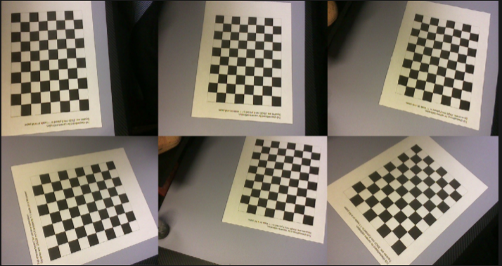
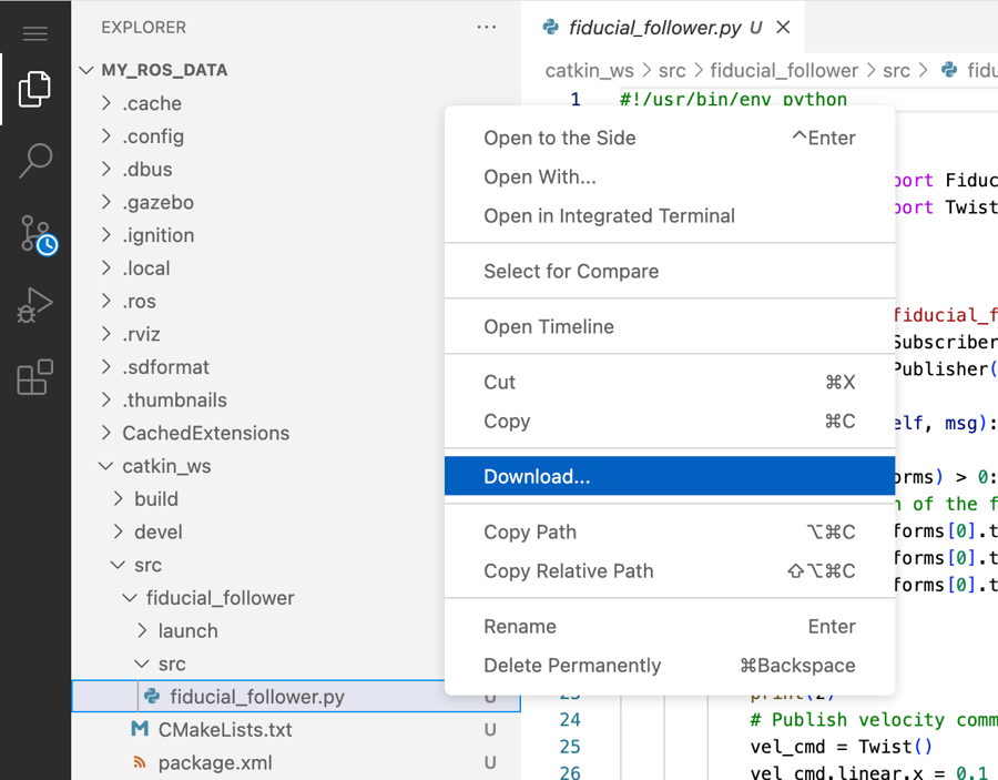

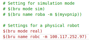
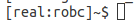


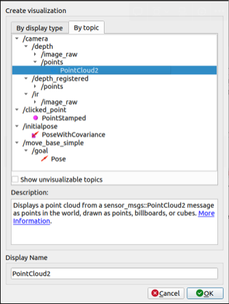
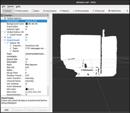
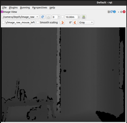


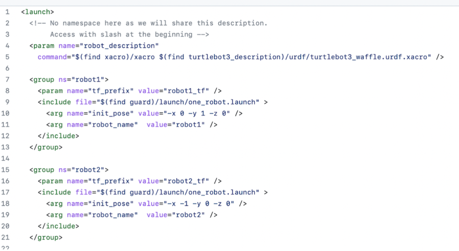
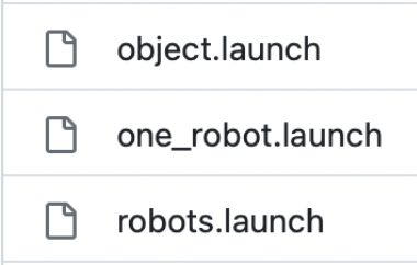
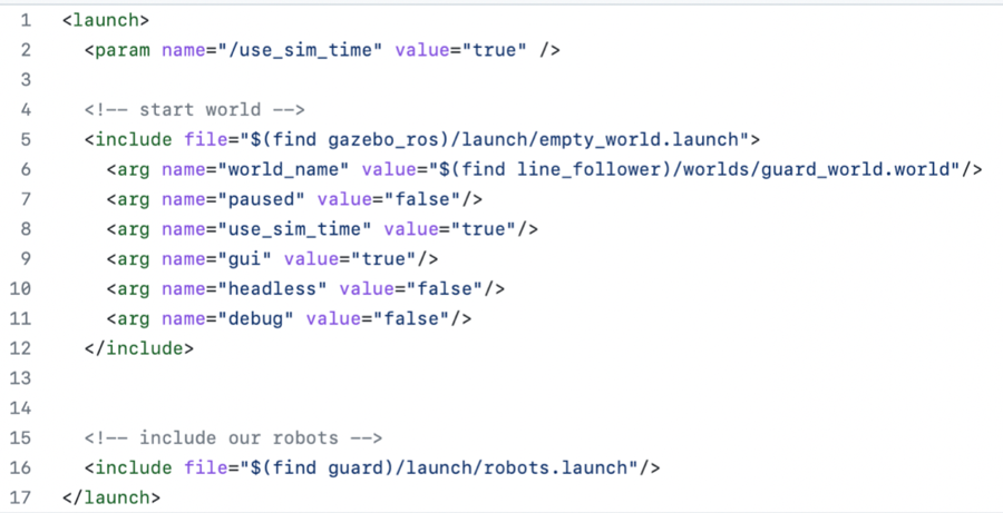
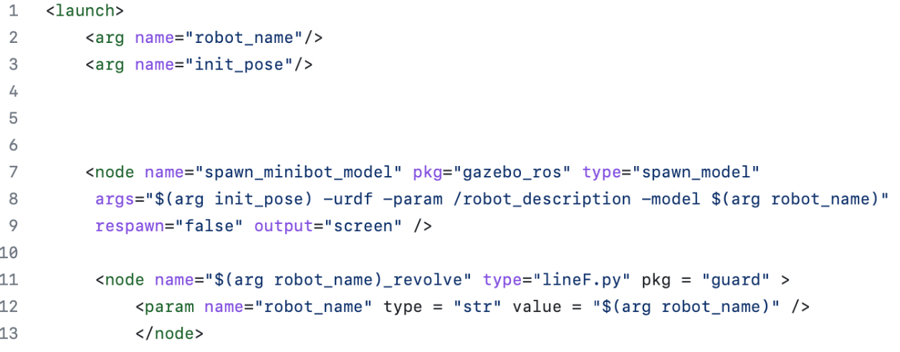


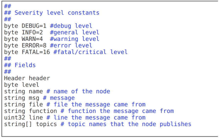
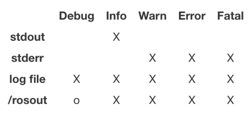
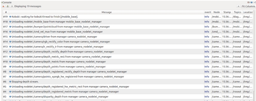


