
robot-arm.md
Final Project Arm Interfacing
Jacob Smith COSI 119a Fall 2019, Brandeis University
Github Repository: [Arm Interface Project](<https://github.com/campusrover/Robot-Arm-Interface)
Introduction and Relevant literature
The goal of this project was to implement a robotic arm to the campus rover. The scope of the project was planned to go from the high level details of a ROS package and nodes to the low level servo commands to control the motor and everything in between. The final goal of the project was to use the arm in a campus rover application.
Adding an arm not only increases the possible behaviors of the campus rover, but created a framework to integrate any electronic component. In addition, it allowed the testing of the concept of interfacing by seeing if a user not familiar with the arm can control it with ROS.
The author already had a background in Arduino Programming. The main source of information for this project were online tutorials and electronics forums and consultation with Charlie Squires (see Appendix A). For the evaluation of the arm's performance, I two publications on evaluation of robot structures and measuring user experience where consulted [1,2].
The requirements of the project where to interface the ROS based campus rover with a four servo robotic arm and an ultrasonic distance sensor. The servos can each move half a rotation at any speed using the VarSpeedServo library [8], and the ultrasonic sensor returns the distance in inches when requested. Both components are interacted using the Arduino microprocessor attached to the arm. That microprocessor is attached to the Rasberry Pi that is the main computer of the campus rover. The goal of the project was to allow these components to communicate with each other and to integrate into ROS, which is explained next.
Technical descriptions, illustrations
The final project is a comprehensive electronics interacting system that allows the arm, manipulator, and distance sensor to be controlled using ROS framework using abstractions. The interfacing scheme is represented below, and could easily be expanded for other electronics components. The main concept is to separate the command of a component from the low-level instruction, similar to how a user can publishcmd_vel and control a dynamixel motor. The figure below represents the existing commands that can be sent to the arm, utilizing both inputs and outputs.
Get Distance
Published to Arm Response topic
Automatic
Distance
Type Output Sensor
Set Arm Coordinates
ARM x y base power
set_arm(100, 200, 90, 0 servoSpeed);
4 coordinates, speed
Type 4 Coordinates
Set Manipulator
MANIP setting
manipulator(true =open/false =code);
open or close
Type Binary Manipulator
This report will now explain the components of the project in a top-down order, as a potential user of the arm would view it. These components consist of: the startup scripts, ROS Publisher, ROS Subscriber, Arduino Program, and the hardware being interfaced with.
The startup scripts allow the appropriate ROS nodes to start and allow the arm to be controlled by a ROS Publisher. These are important because they provide information on how to use the arm to someone unfamiliar with Serial and ssh connection issues.
The ROS Publisher publishes to the armcommand topic. The command is formatted in terms of a component tag, along with integers for required parameters. For example, MANIP 1 closes the hand or ARM 0 330 0 20 20 extends the arm at low power. The python node below waves the arm when a face is shown below, and shows how simply the arm can be controlled in ROS.

The Arm Interface Node is run locally on the Rasberry Pi on the robot because it needs to communicate to the Arduino. This node establishes the Serial connection to the Arduino on the arm ( returning an error message of the arm is unplugged and attempting to reconnect). Then, the node subscribes to the armcommand topic. When a command is published to that topic, the callback function of the subscriber sends the command to the Arduino and publishes the feedback from the Arduino to the ArmResponse Topic. The graph of ROS nodes demonstrates the chain of arm interface and response nodes.

Finally, the Arduino Program running on the Arm itself sets up the program to run the motors and distance sensor, establish the serial connection, and parses data coming over the serial connection. This is accomplished by reading the tag and waiting for the correct number of integer arguments. For example, if "ARM" is received, the program loads the next four arguments received into an array and makes a function call to move the arm position. The program to control the manipulator is shown below, note how it hides the actual degree measurements on whether the servo is open or closed and returns an error message if the improper command is specified.

Then, the Arduino commands the motor to move to the specified angle and returns the distance sensor reading (The heartbeat doubles as the distance reading). The arm and associated reverse kinematics program was provided by Charlie Squires (with the author rearranging the microprocessor and battery connection so the arm could be removed from its original mounting and added to the robot).

Next, a survey of interesting problems and techniques is presented. One persistent and surprising problem with the project was the USB connection between the raspberry Pi and the Arduino. Firstly, the USB needs to be unplugged for the arm to be connected properly, and the arm doesn't check which USB port it's plugged in to. These problems could be solved with a voltage regulator and a modification to the arm interface node to check a list of possible usb ports.
An interesting challenge when integrating the arm into the facial recognition project (see below) was when the arm command topic was being published many times a minute, faster than the arm could actually move. This problem doesn't occur with cmd_vel because the motor moves continuously, while the arm's actions are discrete. We solved the problem with a node which only requests to move the arm every few seconds.
In terms of the Arduino program, it uses the simplest form of Charlie Squire's kinematics program, and that could be abstracted into an Arduino library for code clarity. Currently all commands do not stop the execution of the Arduino program, meaning that the program doesn't wait for the arm to finish moving. This allows the components to be redirected on the fly.
Finally, one must consider how the project can be extended to other electronics components, such as a second arm or a package delivery system. In future work, sensors and a ROS action could be implemented to allow for more complicated movements, such as an action to grab a package. That would be implemented by finding the location of a package, and perhaps using a camera to calculate its location. That location could then be passed into coordinates and published to the arm command topic.
Story of the project
I completed this project individually, but benefited from the support of Charlie Squires, both from his original work on the arm and his advice throughout the project. He remounted and fixed the arm, added the ultrasonic sensor, and was a helpful consultant. Late in the project, I also was able to work with Luis and Chris. Chris and I worked quickly on a proof of concept showing how the behavior trees can be used in connection with the arm, and with Luis we where able to prepare our facial recognition-arm demonstration (See videos Appendix A).
Next, the workflow of the project will be discussed, taking a bottom-up approach. First, I wrote an Arduino program to print output over the USB cable, and a python program to read the output from the raspberry pi. Then in version two, I had the Raspberry Pi write to the Arduino, and when the Arduino received a character, it would open and close the manipulator. Next, I improved the Arduino program to open or close the gripper based on whether an 'o' or a 'c' character was sent by the raspberry pi, which also printed output from the Arduino. This is an example of two way communication between the Arduino and the Raspberry pi. Then, I added the ability to move the rest of the servos in the arm.
With the basic infrastructure in place to control, I converted the python program on the Raspberry Pi to the ROS arm interface subscriber and added more error handling. I then wrote a simple ROS node to publish commands to the subscriber. In other words, in the first part of the project I allowed the arm to be controlled from the raspberry Pi, and then I used ROS to allow the arm to be controlled with any ROS node.
The record of the stages of networking the components of this project will prove useful to the student who wishes to learn about the low level details of interfacing (Arduino Library Example V1-V4 and Raspi V1-V4 in 1). Finally, I made the interface general by creating the tagging system of component and arguments (MANIP 0), which can be easily extended to other components, such as the ultrasonic sensor which reports the distance to the ground.
A major goal of the project was to see how useful it is to people not familiar with Arduino who want to contribute to Campus Rover. To that end, I verified the bash scripts with a TA for the class, who was able to get the arm running using my instructions. In addition, Luis was able to control the arm just by publishing the the arm command topic, and not going to a lower level. This integration with the facial recognition project also allowed me to make the program easier to use and port into another project.
Problems that were solved, pivots that had to be taken
The main problem of this project occurred when a piece of hardware didn't perform the way I expected it to. It was easy to get sidetracked with the details of exactly how a servo works compared to the higher level architectural details.
One pivot during this project was the realization that the servos have no ability to report their angle to the user. I investigated the Servo library I am using, VarSpeedSevo to determine the isMoving function could at least return whether the motor was moving, but my testing showed that it couldn't detect this [9]. Plotting the number of times the servo moved by different degrees shows that there is no correlation between where the servo is jammed and what the isMoving function returns. The lack of feedback data made implementing a ROS action less feasible, because an action should be able to know when it is finished. This is an example of the kind of investigation that the next user of the arm interfacing project should hopefully be able to avoid.

Another problem was the mounting of the arm, as the campus rover was not designed to have a place for it. I initially mounted it above the lidar, but we ended up mounting it on top of the robot (see videos in Appendix A). Hopefully the next iteration of campus rover will include a mount for the arm that is stable and doesn't interfere with the lidar.
Assessment
Overall, I believe the project was a success. The robotic arm is now mounted on the campus rover and can be controlled with ROS commands. In addition, the project presents an on overview of related problems and should be a strong foundation for other hardware additions to the campus rover robot.
The next step of the project would be to add rotation sensors to the arm and write a ROS action to control them, but that should be feasible for the next user now that the main layout is in place. Finally, my main intellectual challenge was thinking architecturally, as this is the first time I had to create a generic system that could be used after me.
In conclusion, I wish to thank the COSI 119a TAs, Professor Salas, and Mr. Squires for their support of this project, and I hope future students find my work useful.
Appendix A: Links and Sources
Sources
[2] Facial Recognition and and Arm Interfacing
[3] Behavior Trees and Arm Interfacing
[4] Vemula, Bhanoday. Evaluation of Robot Structures. 2015 https://www.diva-portal.org/smash/get/diva2:859697/FULLTEXT02.pdf Accessed November 19 2019 [5] Tullis Thomas and Albert, William Chapter 5 of Measuring the User Experience, 2nd Edition 2013
[6] My Original Project Proposal
[7] My Revised Project proposal
[8] (Please see github repository README files for sources)
Videos
Main Project Video

Behavior Tree Integration Video

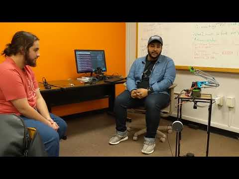
Facial Recognition Video
Last updated
Was this helpful?