Camera Calibration
How to calibrate a camera before using computer vision algorithms (e.g. fiducial detection or VSLAM)
Question
I want to run a computer vision algorithm on my robot, but I'm told that I need to calibrate my camera(s) first. What is camera calibration, and how can I do it?
What is Camera Calibration?
Camera calibration is the act of determining the intrinsic parameters of your camera. Roughly speaking, the intrinsic parameters of your camera are constants that, in a mathematical model of your camera, describe how your camera (via its interior mechanisms) converts a 3D point in the world coordinate frame to a 2D point on its image plane.
Intrinsic parameters are distinct from extrinsic parameters, which describe where your camera is in the world frame.
So, since calibration deals with the intrinsic parameters of your camera, it practically doesn't matter where you place your camera during calibration.
To hear more about the basics of camera calibration, watch the following 5-minute videos by Cyrill Stachniss in order:
This video, also by Cyrill Stachniss, is a deep dive into Zhang's method, which is what the camera_calibration package we discuss below uses under the hood.
How Can I Calibrate my Camera?
This note describes two ways you can calibrate your camera. The first is by using the camera_calibration ROS package. This is the easier approach, since it basically does almost all of the work for you. The second is by using OpenCV's library directly, and writing your own calibration code (or using one in circulation).
The camera_calibration Package
camera_calibration PackageThis guide assumes you've already got your camera working on ROS, and that you're able to publish camera_info and image_raw topics for the camera. If you need to set up a new usb camera, see this entry in our lab notebook.
First, let's install the package:
Second, print out this checkerboard on a letter-sized piece of paper.
Third, tape the corners of the paper to a firm, flat surface, like the surface of a piece of cardboard.
Fourth, measure a side of a single square, convert your measurement to millimeters, and divide the result by 1000. Let's call your result, RESULT.
Now, let the number of rows of your checkerboard be M and its number of columns N. Finally, let's say your camera node's name is CAM, such that, when you connect it with ROS, it publishes the /CAM/camera_info and /CAM/image_raw topics. Now, after ensuring that these two topics are being published, execute:
Next, follow the instructions under section 4 "Moving the Checkboard", and section 5 Calibration Results of the official camera_calibration tutorial.
WARNING The two sections stated above are the only ones you actually want to follow in the official tutorial. Much of the rest of the material there is outdated or misleading.
Here's a video of what a successful calibration process might look like.
OpenCV
Sometimes, you might want to use object detection or use certain algorithms that require a camera such as VSLAM. These algorithms usually require a very good calibration of the camera to work properly. The calibration fixes things like distortion by determining the camera’s true parameters such as focal length, format size, principal point, and lens distortion. If you see lines that are curved but are supposed to be straight, then you should probably calibrate your camera.
Usually this is done with some kind of checkerboard pattern. This can be a normal checkerboard or a Charuco/Aruco board which has some patterns that look like fiducials or QR codes on it to further help with calibration. In this tutorial, we’ll be using a 7x9 checkerboard with 20x20mm squares: checkerboard pdf.
The most ideal way to do is to print the checkerboard on a large matte and sturdy piece of paper so that the checkerboard is completely flat and no reflections can be seen on it. However, it’s okay to just print it on a normal piece of paper as well and put it on a flat surface. Then, take at least ten photos with your camera from a variety of angles and positions so that the checkerboard is in all corners of the photos. Make sure the whole checkerboard is seen in each picture. Save those photos in an easy to find place and use the following to get your intrinsic calibration matrix.
The code I used was this opencv calibration. It also has more notes and information about what the information you are getting is.
Step by step:
print out checkerboard pattern
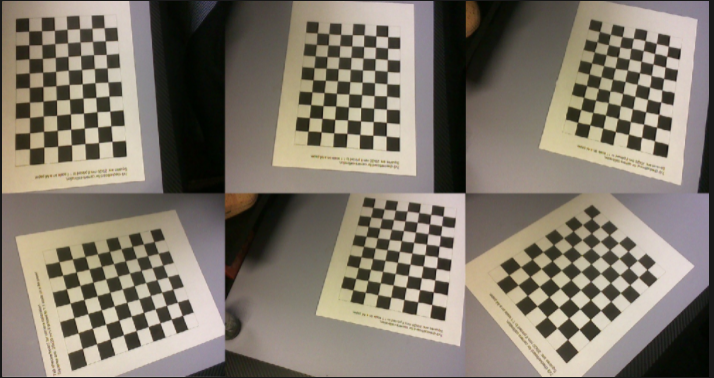
take at least 10 photos of the checkerboard at a variety of angles and positions (see image 1 for examples) and save in an easy to access place
download/copy the opencv calibration code and run it after changing the folder path
get the intrinsic matrix and distortion and enter it into whatever you need

Image 1: some examples of having the checkerboard cover all corners of the image
Potential intrinsic matrix:
[[688.00030953 0. 307.66412893]
[ 0. 689.47629485 274.053018 ]
[ 0. 0. 1. ]]
Pastable into python:
fx, fy, cx, cy = (688.00030953, 689.47629485, 307.66412893, 274.053018)
Distortion coefficients:
[9.39260444e-03, 4.90535732e-01, 1.48962564e-02, 4.68503188e-04, -1.77954077e+00]
Last updated
Was this helpful?
